Computer aided cutting
Project 2 in Computer aided fabrication
Intro
Project 2 was made up of two parts:
Part 1:
Cutting with a programmable vinyl
cutter. Available materials were 1000x500 mm sheet of vinyl.
Part 2:
Designing parametric pressfit model from more then one building blocks and cutting it out with a
laser cutter. Available materials were 4x500x500 mm birch plywood or 3x500x500 mm acrylic
plastic (plexiglass). Excess cardboard paper from the FabLab and materials we brought ourselves
were also allowed.
Part 1 - Vinyl
Thought process and preperation
I started by creating a table in an Excel spreadsheet to ceep track of my worktime and to categorize it. Then I browsed YouTube for ideas for the vinyl cutter. Or that was the purpose at least. I used the search words "vinyl cutter" and found this video about how to operate a vinyl cutter. I found the video informing but not very inspirational. That was okay though because I had an idea. I could use the vinyl cutter to make logo stickers for my newfounded company Zerobars ehf (website will be linked when it's ready).
Next step was to download Inkscape and to get to know it a bit. I tried some buttons, read some descriptions, drew some shapes and even tried to import .jpg files. When that was done I decided that the preperation was over and I sould move to designing the stickers.
Worktime: 2 hours.
Creating cutting path
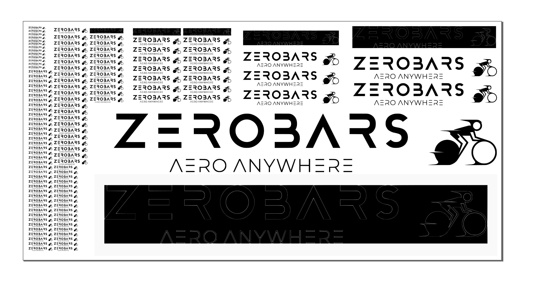
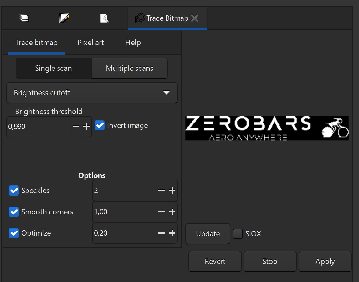
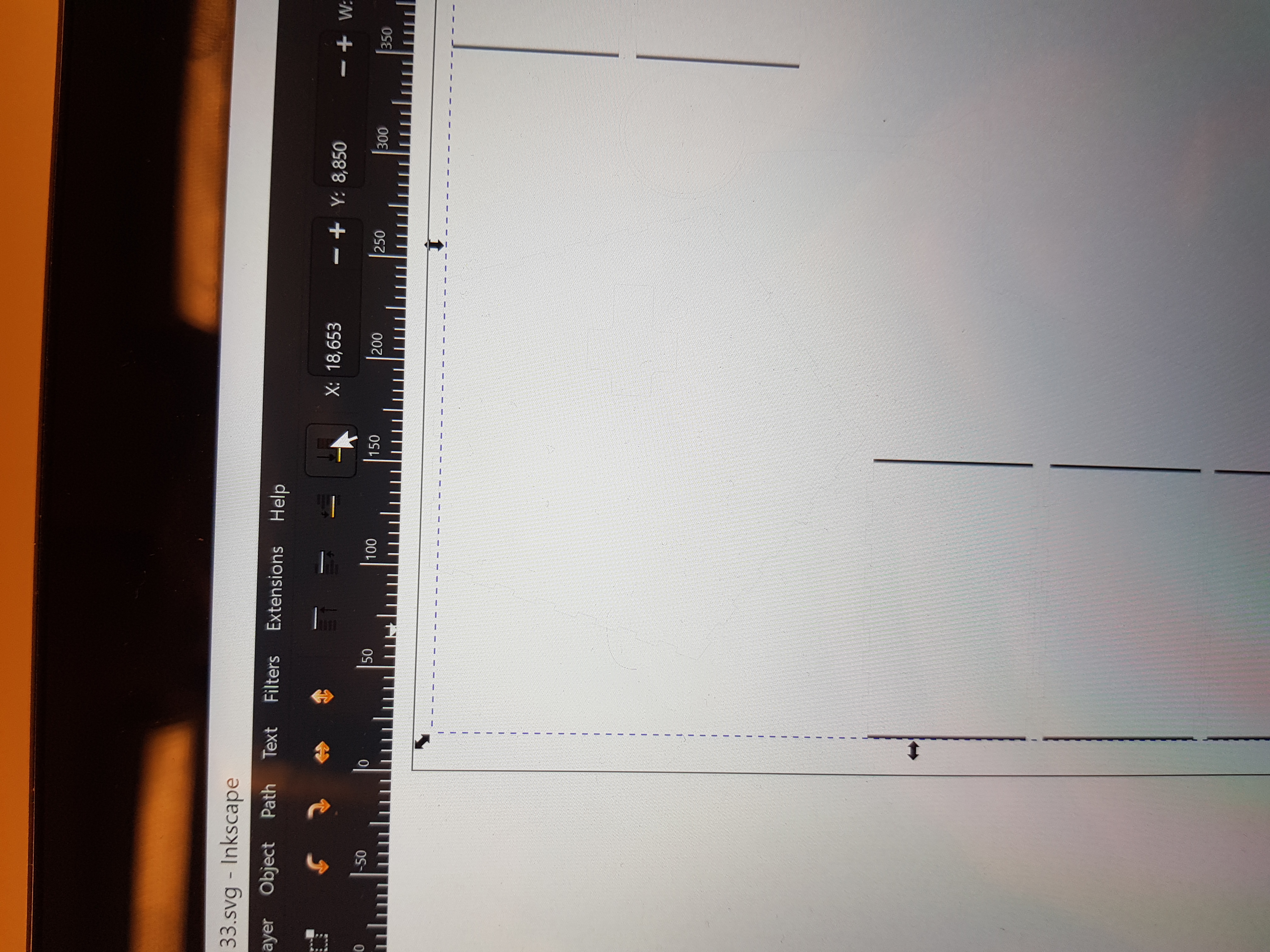
I descided to use this project to create stickers of the logo of my startup company: Zerobars. I started by opening Inkscape and importing a .jpg file of the logo. Then I opened "Document properties" and changed the page size to 1000 x 500 mm. I copy-pasted the logo many times over, resized some of them and draged around until I had reached an adequate usage of the page. The next step was to trace the bitmap of every single image. I played with the "Brightness threshold" and tried values from 0,250 to 0,990. I think the 0,990 value will be better in the end, but we will see when I run it through the cutter. I also experimented with inverting the image. I don't know whether that will work or not, but it is worth the try.
Worktime: 1.5 hours.
Fixing the cutting path
When I arrived at the FavLab, Hafliði (the instructor) took a look at my dvg file. He showed me that my file did not only include the bitmap of every logo, but also the jpg files behind the bitmaps. It turnes out that when bitmapping, the original image behind isn't deleted so I had to delete all the leftover images. Instead of carefully selecting every image individually and deleting them, I deleted most of the copies of each size, both the image and the bitmap. Then Hafliði showed me a way to make a lot of copies very fast. There is namely a special function in Inkscape to make a lot of copies of an object. That function is called "Clone". There was one issue left. The smaller logos were probably to small to cut do to the shape of the cutters blade. The blade in the cutter is shaped like a regular blade from a knife. Therefore it has a limited turning radius, which at the time seemed like a possible problem. For those reasons, I deleted most of the clones for the smaller logos and only kept a few as a test, but I kept all the bigger ones.

Worktime: 1.25 hours.
Cutting from the vinyl
When the svg file was finally ready for cutting, it was time to set the vinyl cutter up.
I installed a sheet of matt black vinyl and made sure the sheet was under the guiding wheels.
Then I copied the file to a USB stick and opened the file in the PC connected to the vinyl
cutter.
I selected all the entities and pressed CTRL+P on the keyboard (to print the file
to the vinyl cutter).
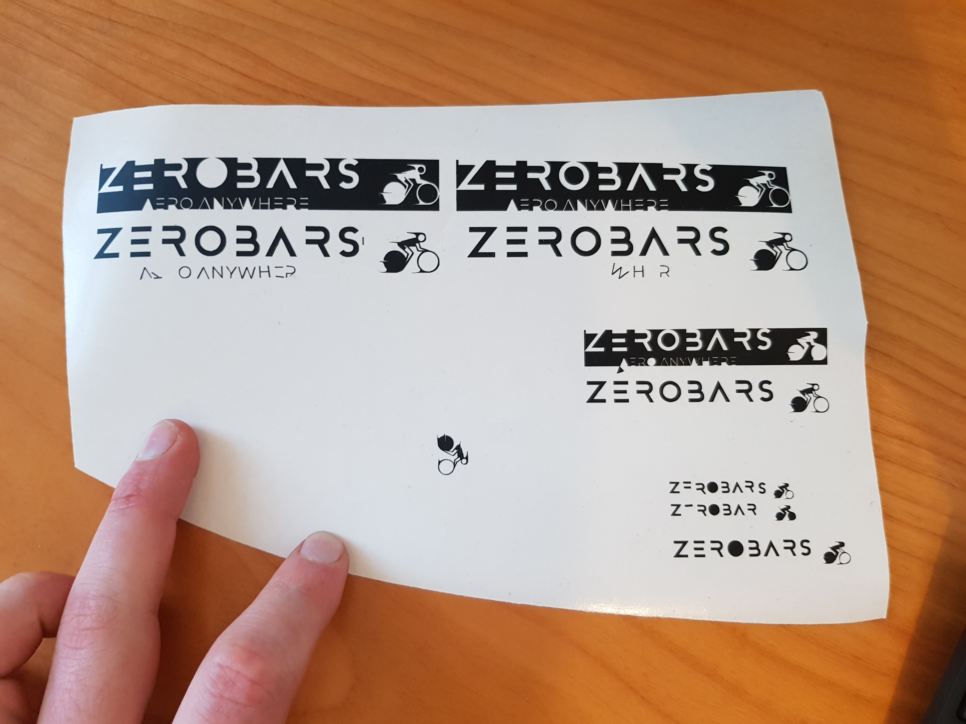
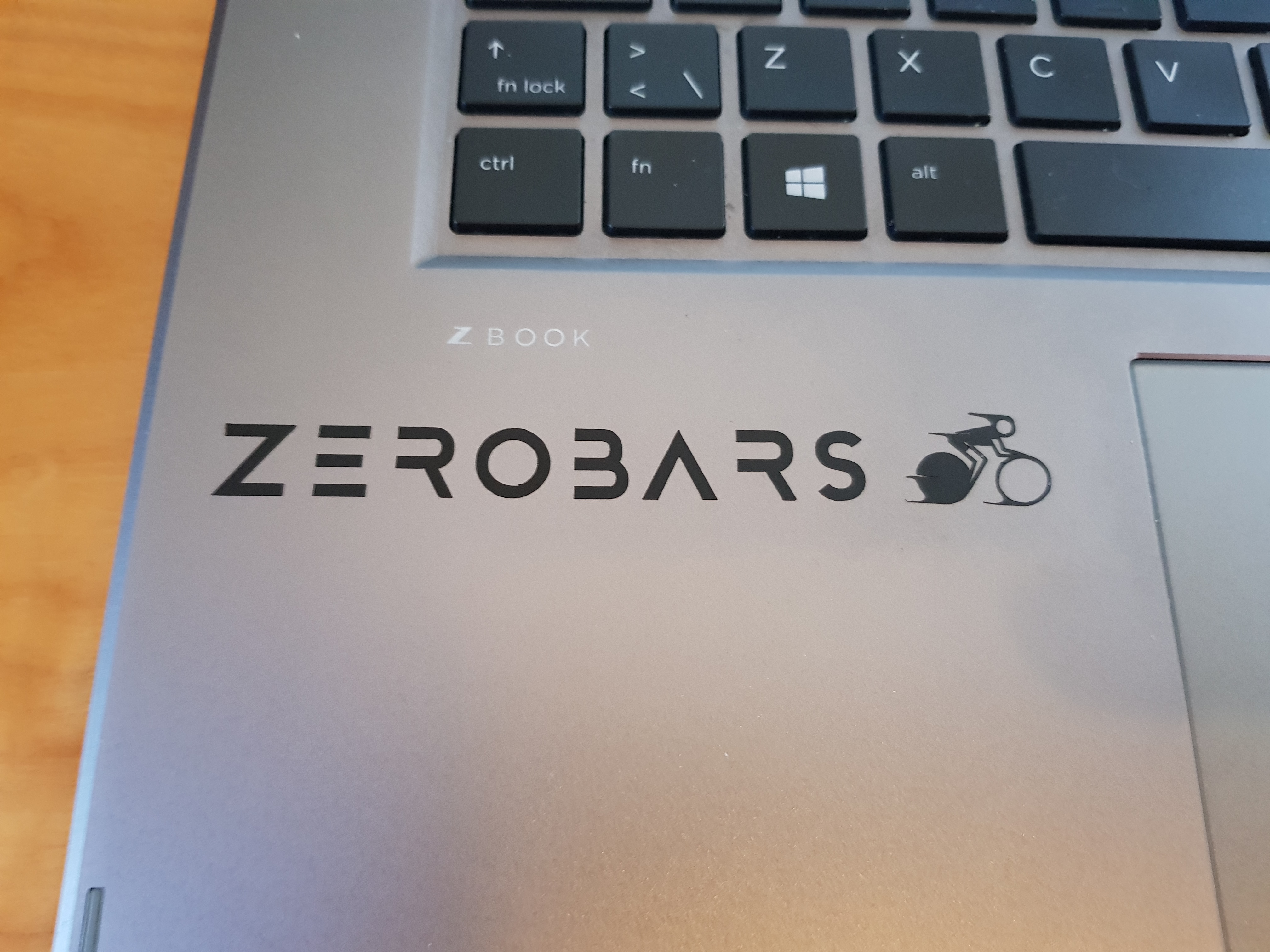
The cutting took a few minutes and was a great success. Next step was to cut a piece of the
vinyl, ply off the excess and try it out.
The smallest ones were a failure as expected but some of the smaller ones were an unexpected
success.
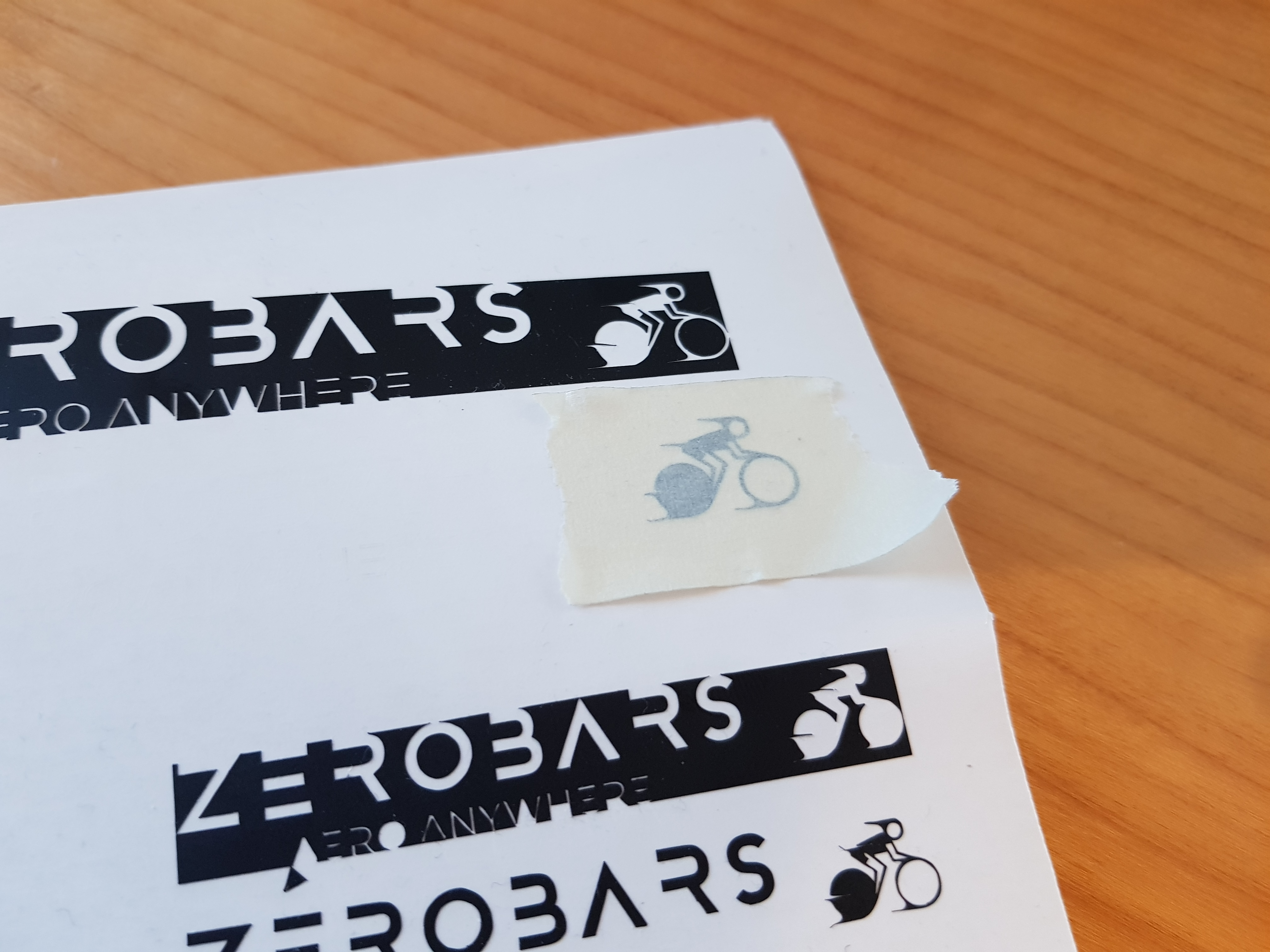
The plying was quite tricky, especially with the smaller logos. I tried using both an acne and a
tablecloth knife, but I found the knife to be a bit better.
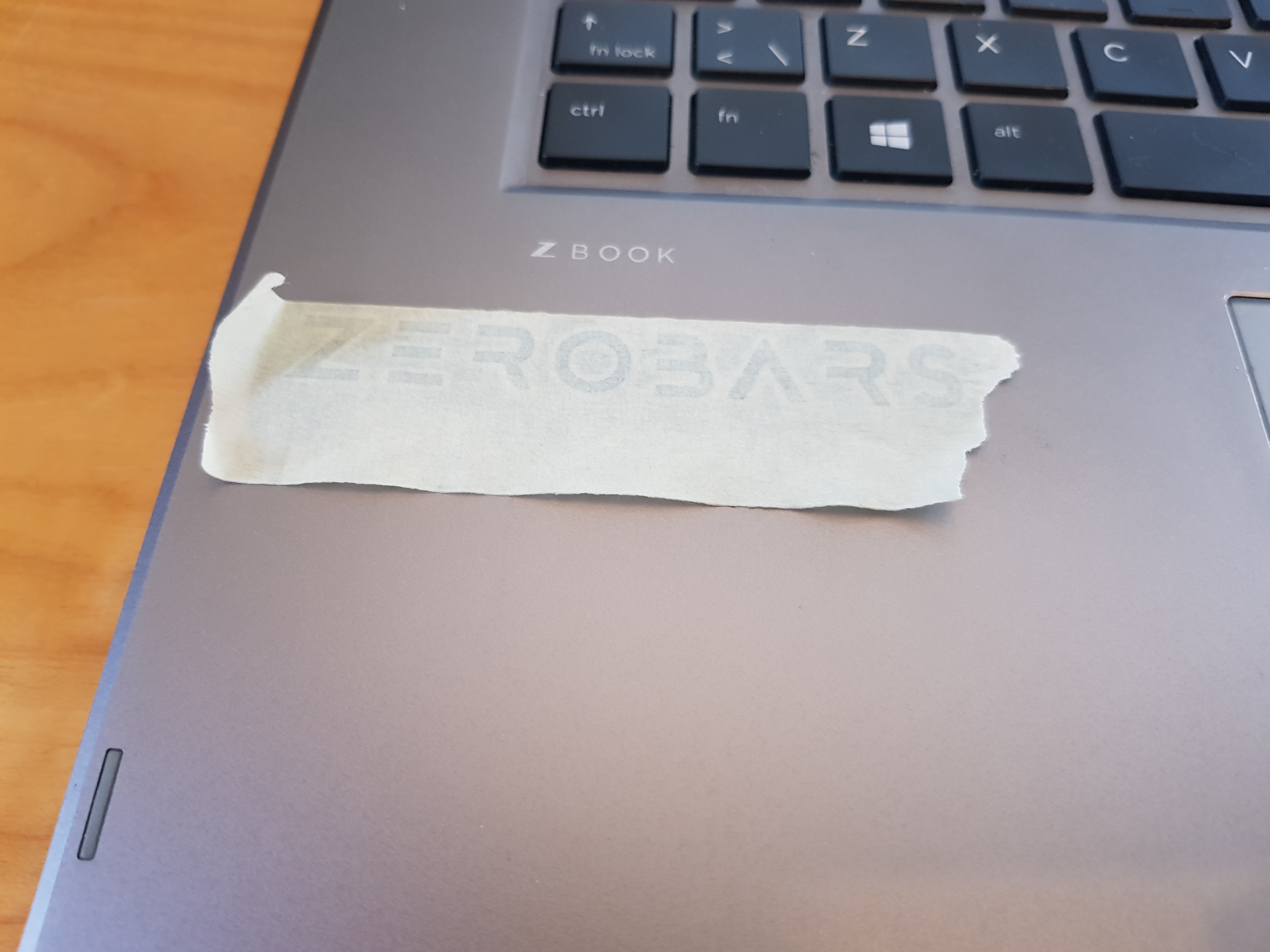
To get the stickers to another surface, I dust had to cover them with a masking tape, pull the
tape carefully off and apply it to the final surface.
Worktime: 1.5 hours.
Vinyl total worktime: 6.25 hours.
Part 2 - Pressfit
Thought process and preperation
I started by browsing Pinterest for ideas for wooden pressfit projects. I used the search words
"press fit plywood project". I found some amazing work and that was really inspirational. The
links are below.
Pinterest
1
Pinterest
2
Pinterest
3
Pinterest
4
Pinterest 5
I am used to using Autodesk Inventor and I am currently in a course about drawing in DS Solidworks but for the sake of spending more time on the project it self, rather than getting stuck on problems due to the difference between Fusion 360 and those programs, I decided to install Fusion 360 on my laptop. Getting the license was really easy because I already had an Autodesk student account. But the downloading and installation still took a long time and I really wanted to make sure that I did not make any mistakes in the installation process.
When Fusion 360 was finished installing I opened tutorials fram Jón Þór regarding parametric design and getting a 3D object on to a laser cuttable 2D format. I followed through the tutorials and made sure to repeat every step myself and that made me understand those actions a lot better.
Worktime: 5 hours.
Measuring Kerf
When using a laser cutter, you have to account for the kerf of the laser, that is the thickness of the cut itself. To measure the kerf, I teamed up with Friðrik Valur and Finnur Mauritz.
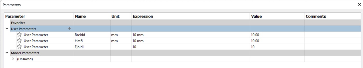
We started by creating a simple drawing of a few rectangles in Fusion 360. Each rectangle was 10x10 mm and the number of rectangles was 9. The reason for that choice was that with 9 rectangles, you have 10 paralell cuts of equal size. That meant that we could make the cut in the laser cutter, push all the rectangles to one side, measure the gap and devide by 10.
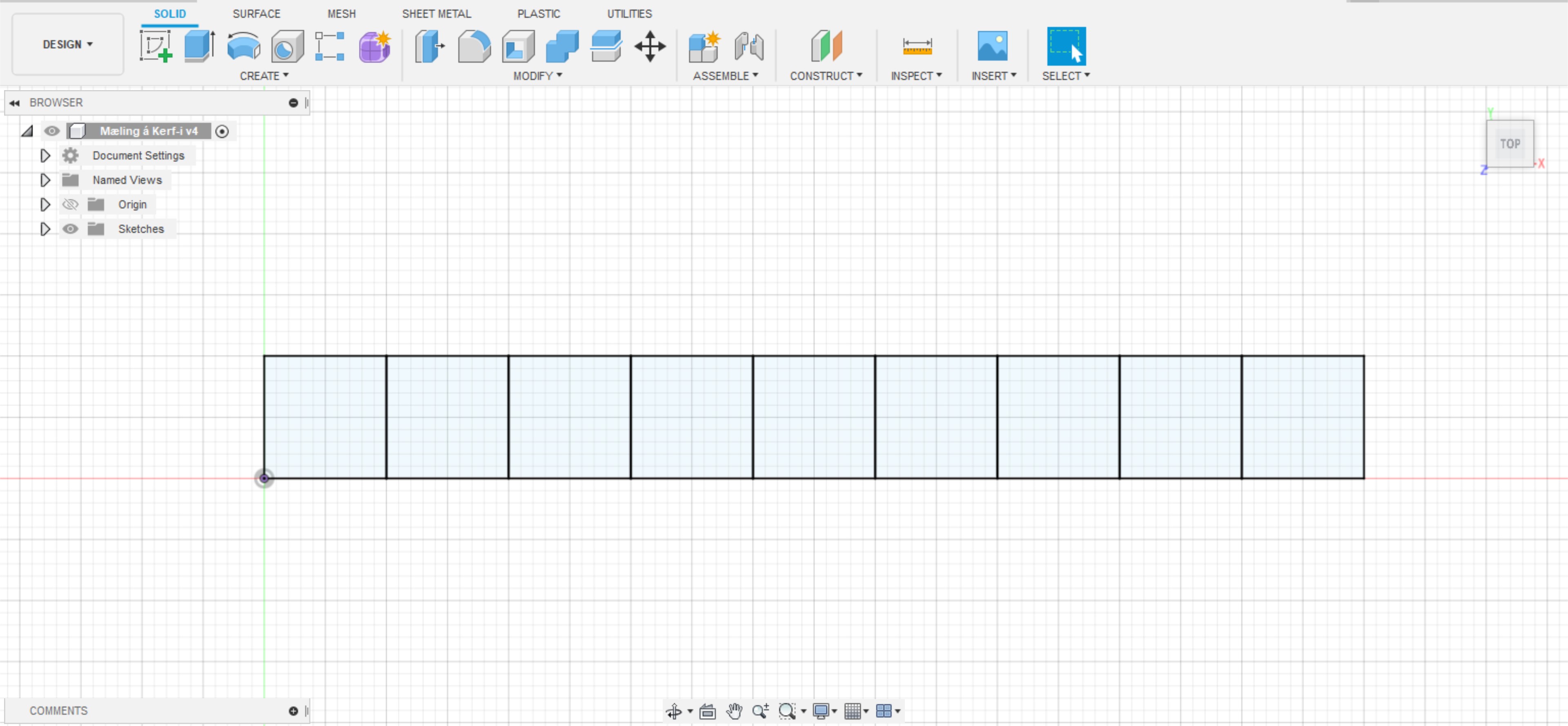
Next step was to export the Fusion file to .dxf format and open it with Inkscape. In Inkscape we found out that we made a mistake in the Fusion drawing. When we drew in Fusion, we drew one rectangle and used linear pattern to make the rest of them, that is we duplicated the first one 9 times automaticly. We should have only duplicated 3 sides of the original rectangle but we selected all of them. As a result we had two lines where there sould only have been one for all the vertical ones except for the ends. But by selecting the duplicated lines in Inkscape and deleting them one by one, we fixed the problem.
Then we selected all the lines in the drawing and adjusted 3 parameters. We set the fill to none, the stroke paint to flat color and the stroke style thickness to 0,020mm. We exported the file once again but this time as a .svg file and we saved it to a USB flash drive.
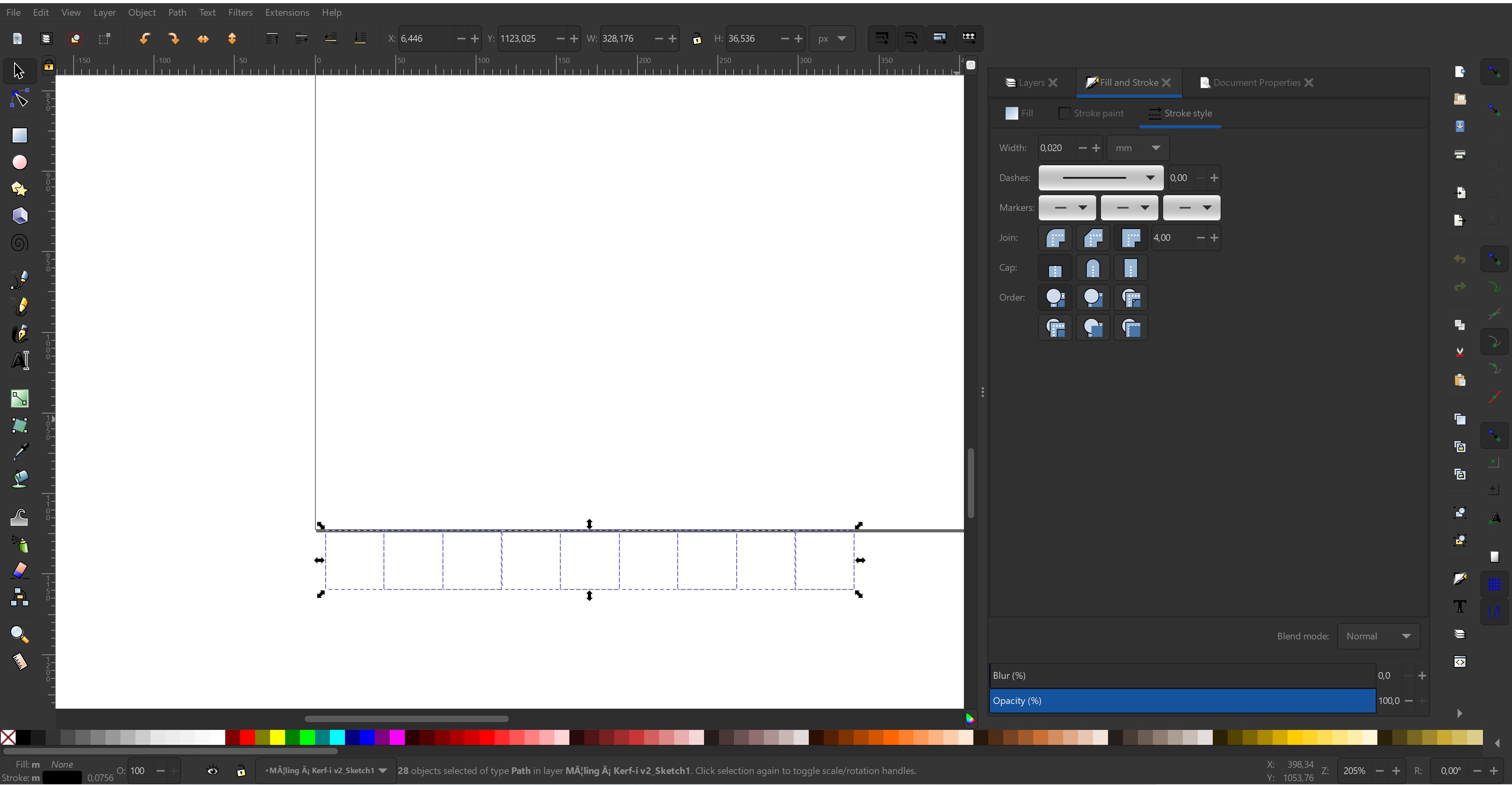
The laser cutter in the FabLab in VR-III was connected to a PC that had the nessecary software already on it to run the laser cutter based on our .svg file. We plugged the USB stick into the PC and opened the file with Inkscape. We doublethecked if all parameters were the same as before and pressed CTRL+P, then ENTER on the keyboard. That took us to the program controlling the laser cutter.
On that stage of our project, we were not sure whether we whanted to use acrylic plastic or plywood so we decided to measure the kerf in both materials. We adjusted the program for plywood and placed a sheet of 4mm thick plywood on in the laser cutter. We positioned the drawing on the plate in the software using a camera feed from the cutter.
The settings in the laser cutter control program were:
| Material | Parameter | Value |
|---|---|---|
| Plywood | Preset | Wood cutting 6 mm |
| Plywood | Speed | 20% |
| Plywood | Thickness | 4 mm |
| Acrylic plastic | Preset | Acryl 3 mm |
| Acrylic plastic | Speed | 30% |
| Acrylic plastic | Thickness | 3 mm |
| Both | Autofocus | Thickness |
| Both | Air outlet | ON |
The last step was to measure the gap with a calliper and divide by 10. Our results were that for the plywood, the kerf of the laser cutter is 0.167 mm and for the acrylic plastic, it is 0.133 mm.
.jpg)
.jpg)
.jpg)
.jpg)
.jpg)
.jpg)
.jpg)
.jpg)
.jpg)
.jpg)
.jpg)
Worktime: 3.25 hours.
First design
At this point in the process, I had descided what my project should be. I was going to make a part of a soup feeding robot from another project in another course. Me and Friðrik Valur were planning on making the robot together. But this project was a solo one, not a team project so we had to split the design and manufacture part (at least the lasercutting and 3D printing) of the robot. I took the base of the robot and Friðrik took the arms of it. I think there is plenty of complicated stuff in the robot to be enough for two very good lasercutting pressfit projects and also for two good 3D printing projects.
An important part of the project was to test the pressfit mechanisms. Friðrik was making rods for the arms of the robot using 3 different pressfit techniques and planned on testing all of them. If, later in the project, my part will need some more tests, then I will also create test files to test those pressfit mechanisms, but since we are designing one robot, we are sharing parameters so the usability of two identical test would be limited. I still think I will have some valid and valuable tests later on.
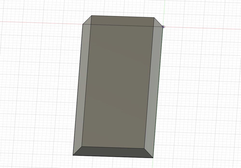
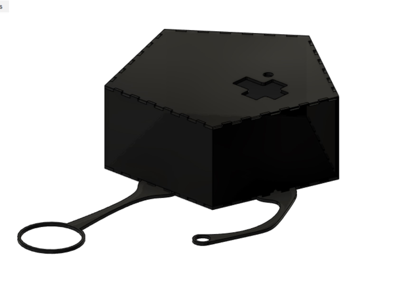
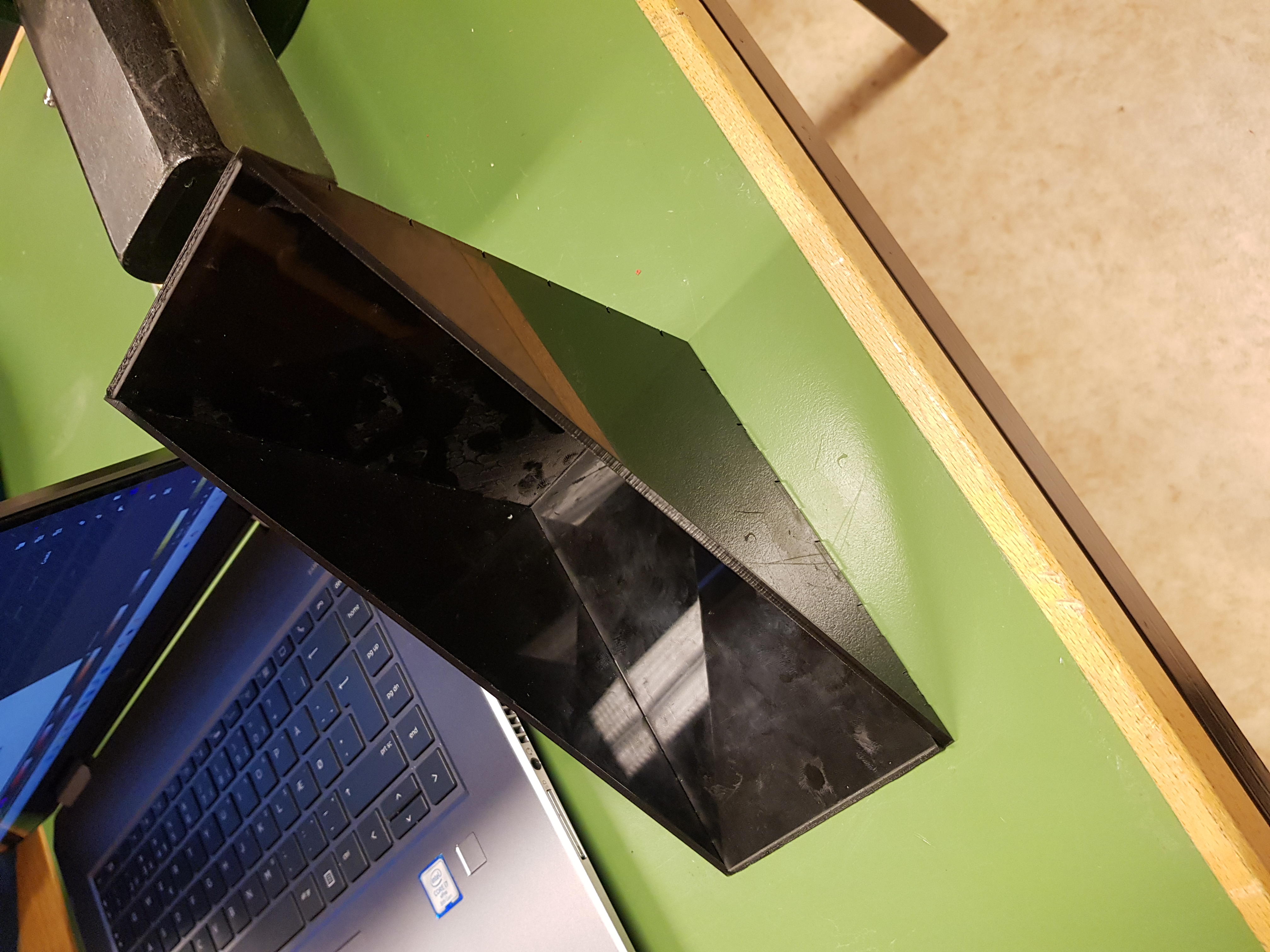
The first idea of a base of the robot was to make it from black acrylic plastic looks like this:
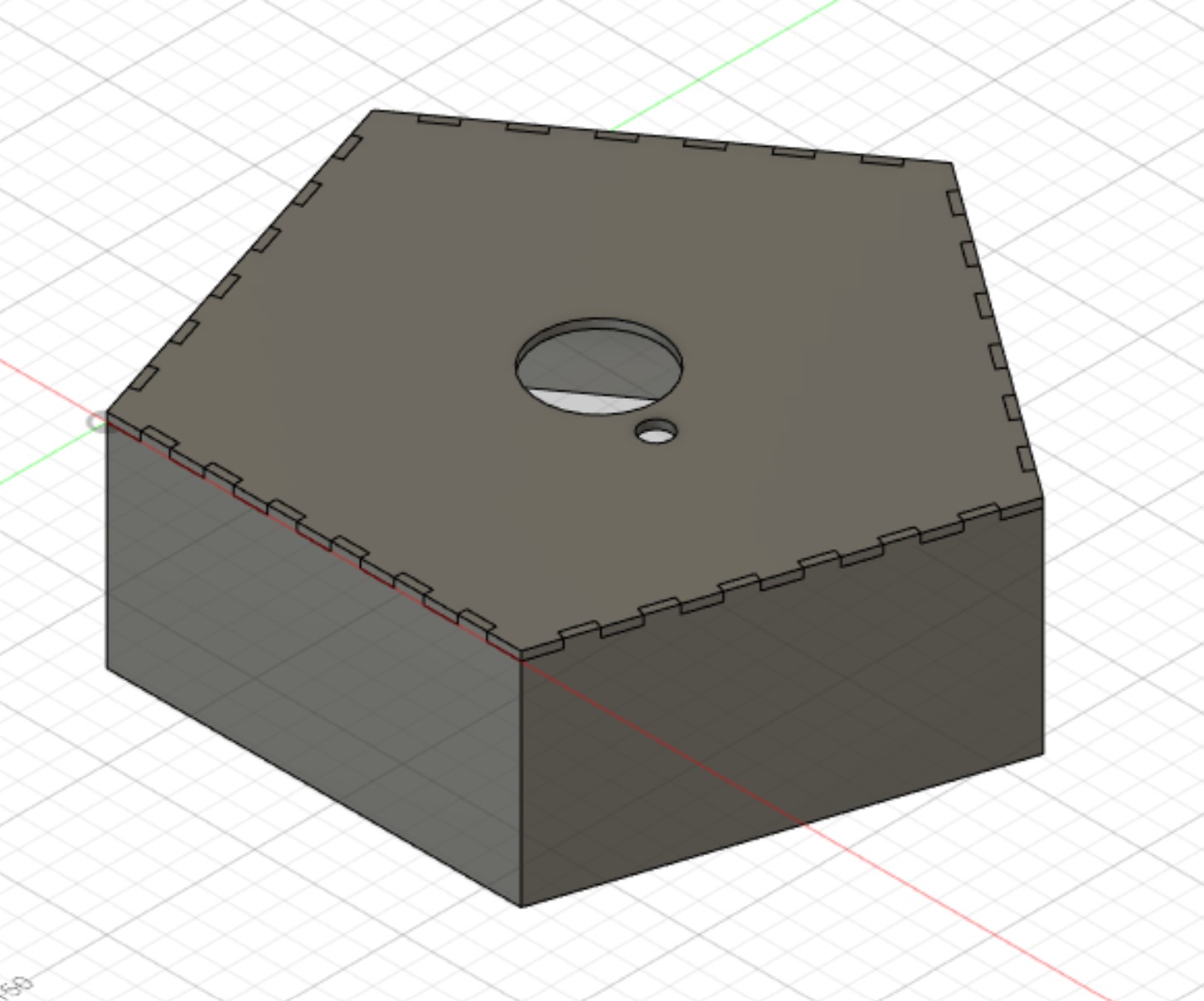
That is a pentagon shaped box with cut-outs for both rotating joint and wires. What was miss there was a base for the base and connections to a soupholder, a fan and possibly some sensors. The placement of the sensors was not determined at that point in time.
I started by creating a sketch in Fusion 360. I used a pentagon shape and added the finger joints using both "Rectangular pattern" and the "Mirror" functions.
.jpg)
All dimensions of the drawing were made using parameters. And some of them were calculations based on trigonometry and other parameters.
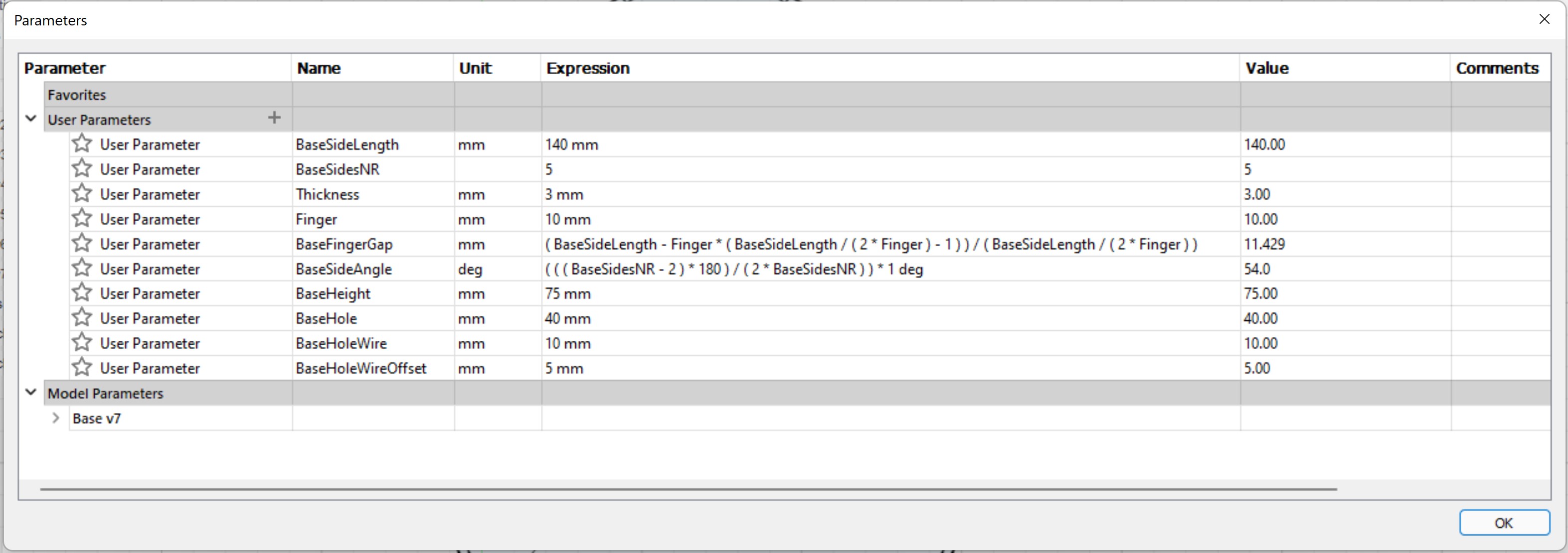
From that sketch I extruded both the top plate and the sides, just like in the tutorial from Jón Þór mentioned above. There was one problem though. Now I had side pieces with ends at an angle and the laser cutter does not cut at an angle.
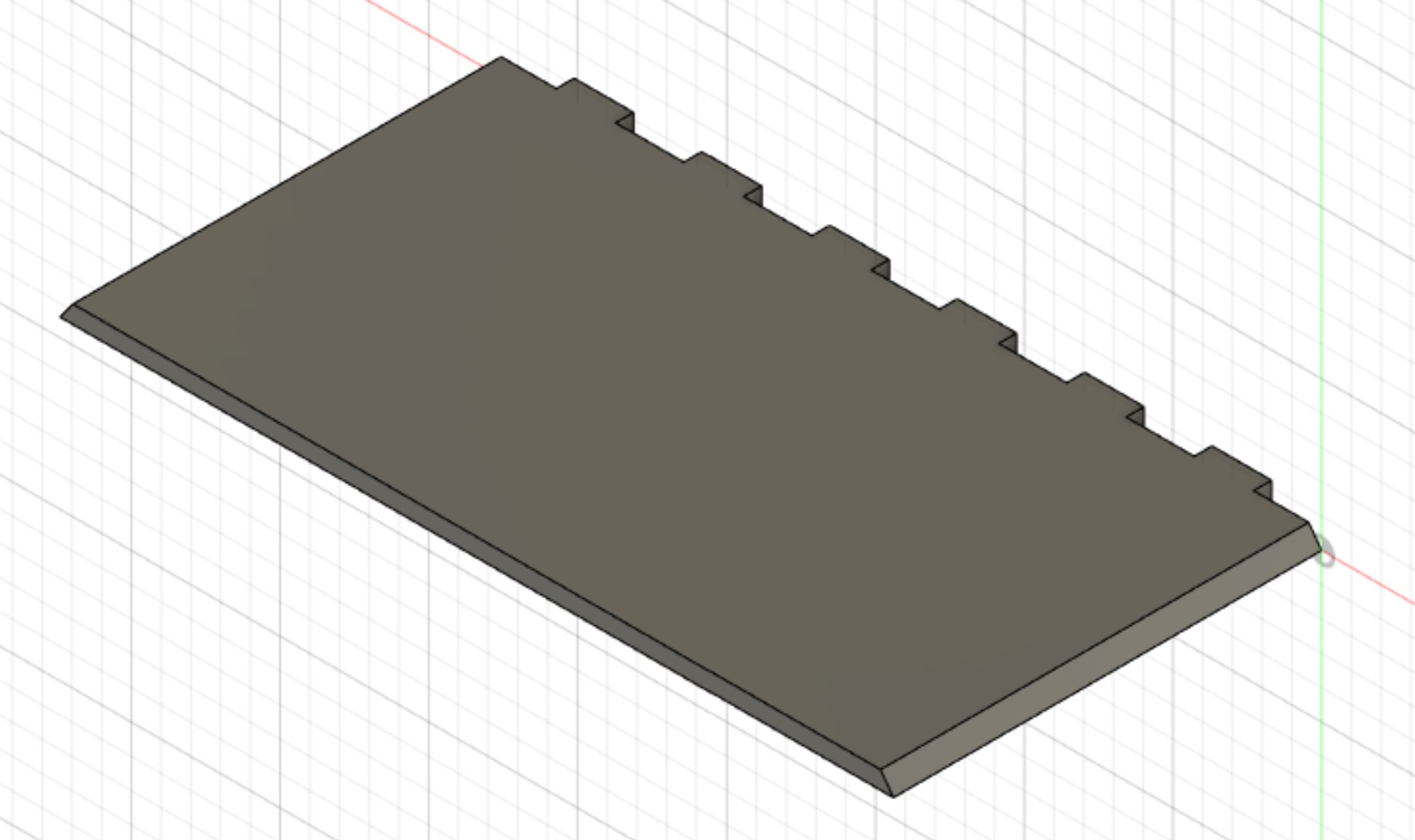
After some discussion with Hafliði, the tutor of the project and teacher of the course, I descided to try to make the slope using gradient input to the laser cutter. That means that the power of the laser will be determined by the darkness of the lines and using a gradient would theoretically create a slope. By taking a look at the parameters, it can be seen that the slope is supposed to be 54°. But before cutting the base in full size, some tests on that were required.
Worktime: 3.7 hours.
Creating slope/gradient tests
To create a slope test, I started by drawing the part I wanted to use as a test pice. I made a 3x20x50 mm and cut the longer ends at an angle of 54° just as nessecary to make a pentagon.
That was not the most efficient way to do the test, it would have been easier to not bother with the corners in Fusion and just make them in Inkscape, but I wanted to test the whole process. In Fusion, I adjusted for the kerf of 0.133 mm and exported as a .dxf file. I opened the file in Inkscape. I immediately saw problems. The top line of the rectangle was split in two parts and on top of that, the corners were rounded so getting the lines to fit was not an easy drag and drop:
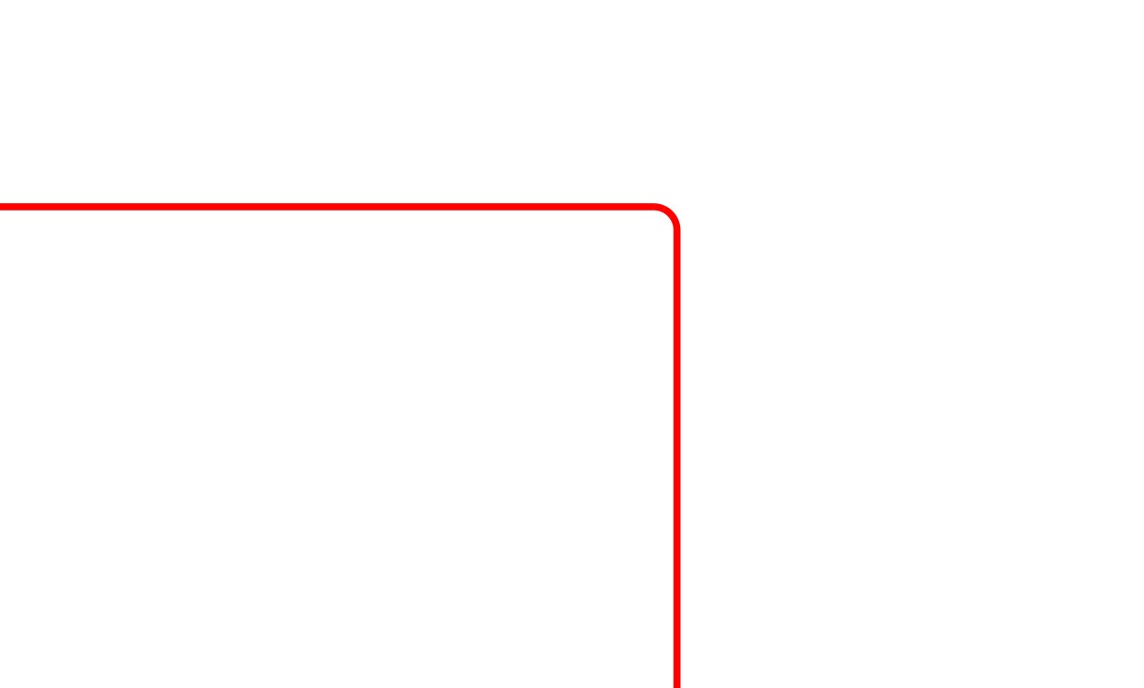
But after some in app measurements and easy calculation, I ended with 4 lines and 4 corners, just like I wanted. Then I created rectangles in which the gradient fill was supposed to go. I only found one way to get an accurate gradient, and that was to use the snaping-mechanism of the corners of the rectangle to get a horizontal line. Then I realized, I should have duplicated the rectangle to the other side before adding the gradient. After fixing that I had a successful test unit, or I thought so.
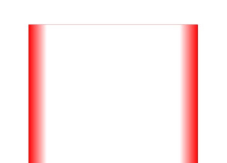
I made a copy of the test unit and changed the opacity down to 50%. Then I duplicated the items to get a set for testing. After that I realized that I should have made it in black, not red. I slammed the undo button, fixed the color and did it all over again. The end result looked like this:
Worktime: 1.15 hours.
Testing the slope
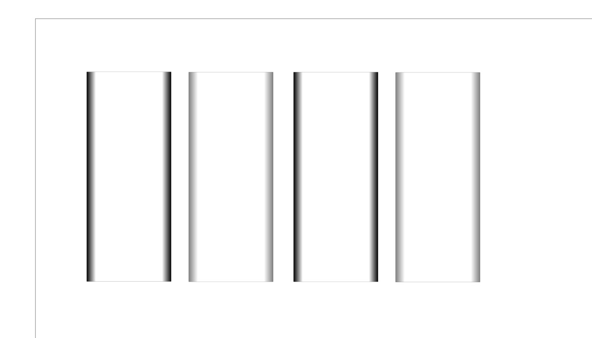
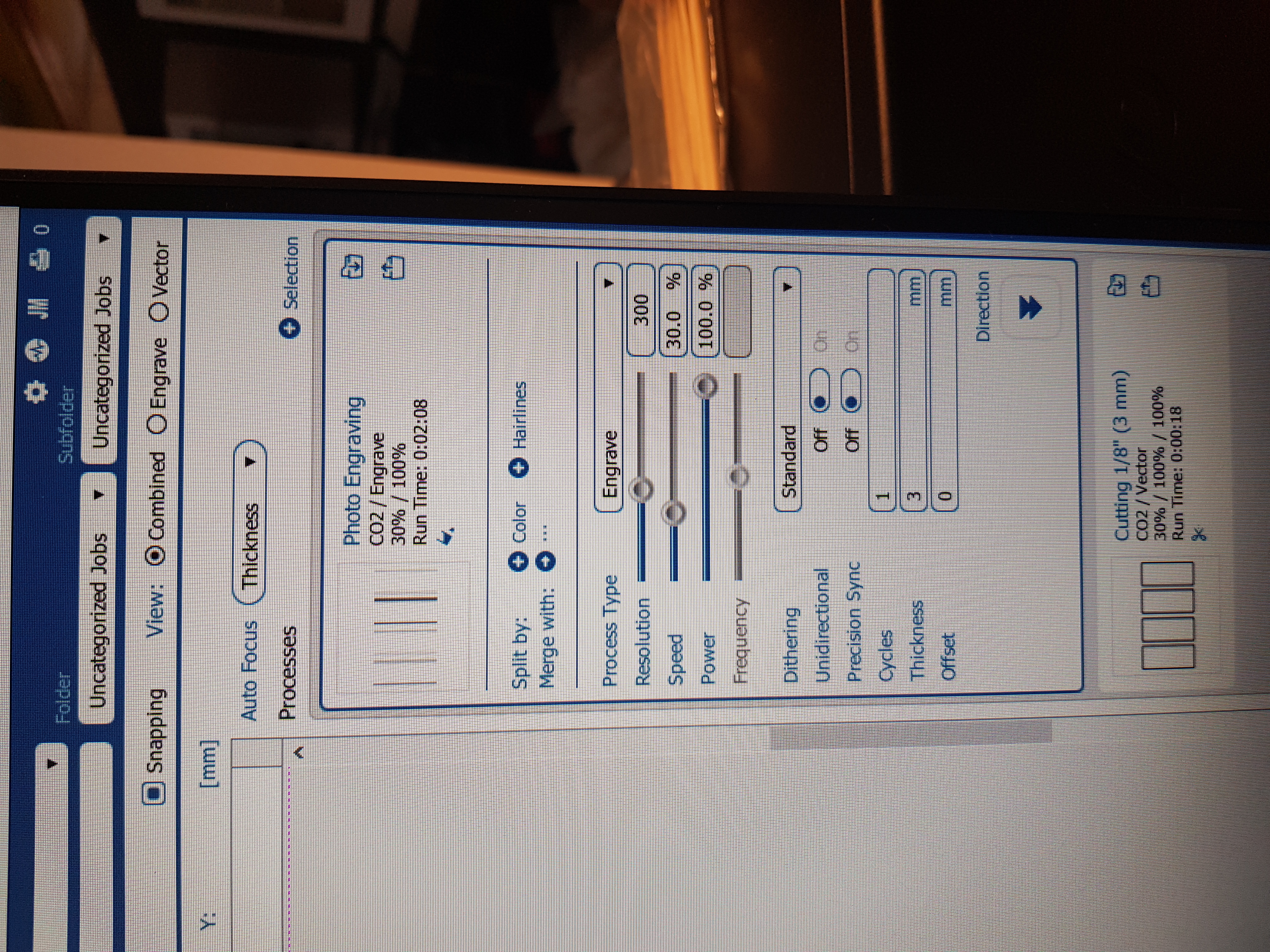
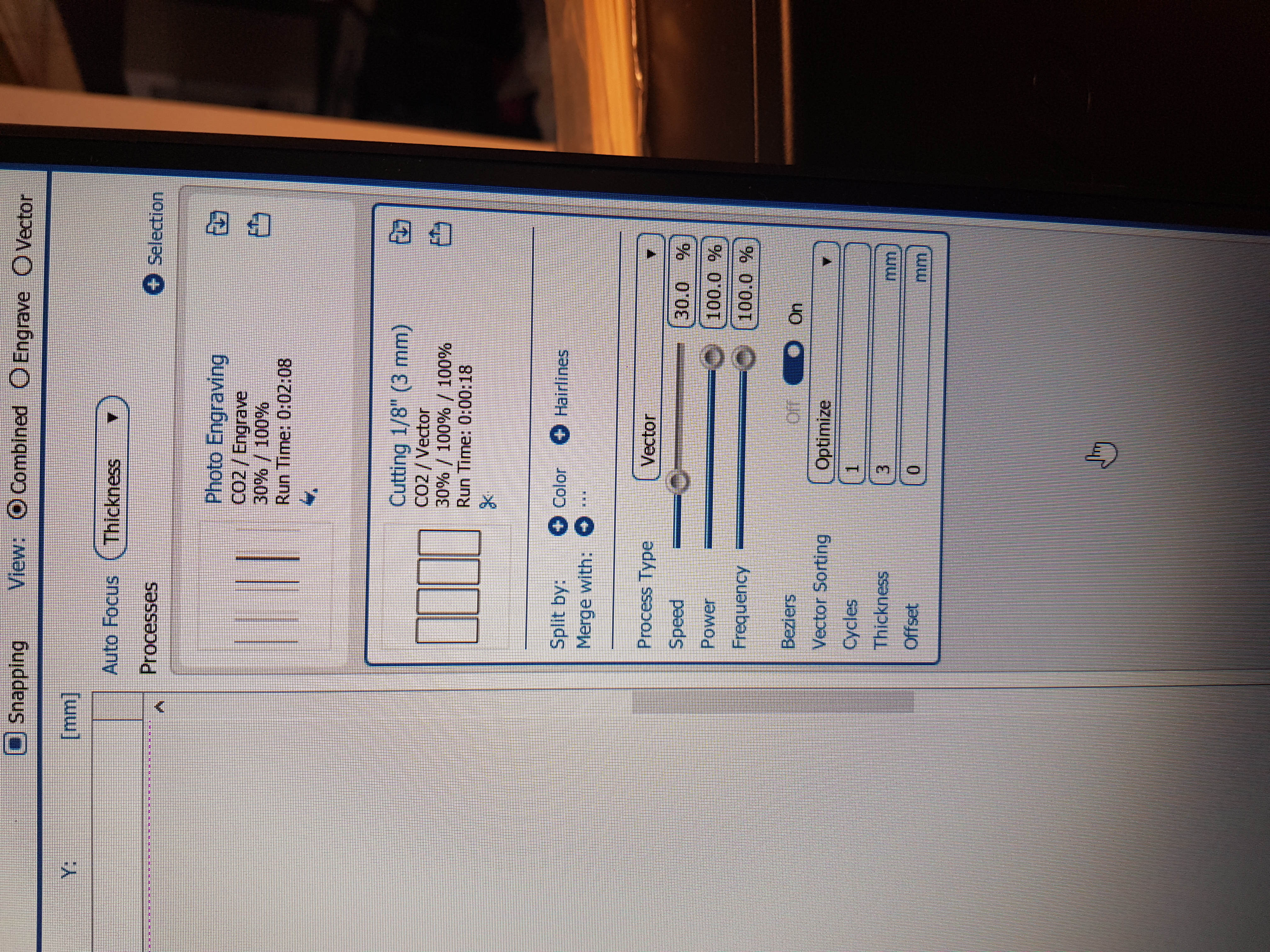
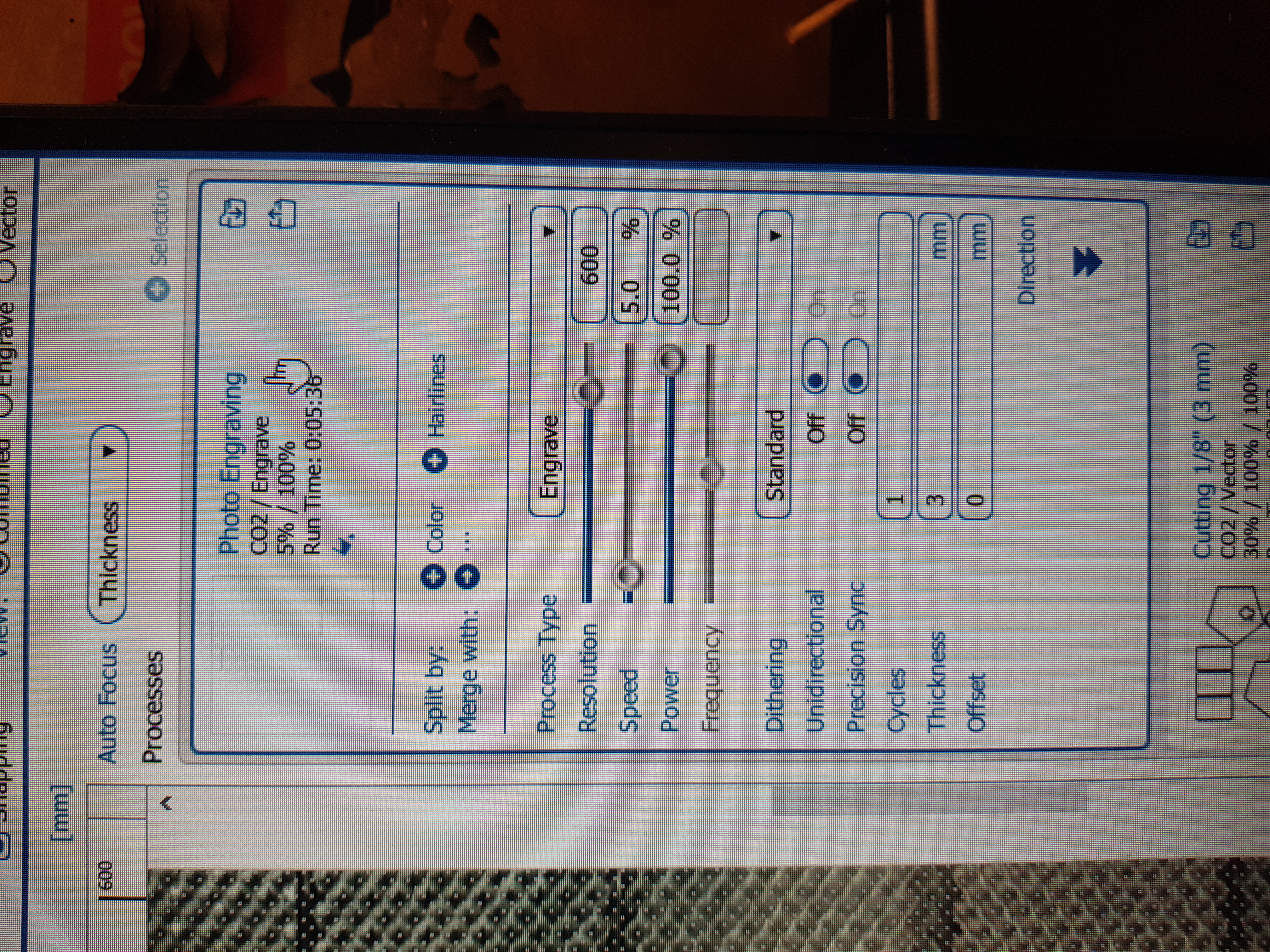
At the FabLab in VR3, I copy-pasted the .svg file (shown in figure above) to the PC connected to the laser cutter. I opened it in Inkscape and printed it out to Epilog Dashboard (the laser cutter driver). When doing so, I realized that the driver was not splitting the file correctly between engraving and vector. To fix that, I went back to Inkscape, deleted all the edges, selected the gradients and exported as .png with the pixel density of 1000 dpi. Then I opened a new file in Inkscape, drag-and-dropped the png image and drew rectangles around the gradients, just like before.
The first test was clearly not a success. The graving was clearly not deep enough and no slope visible.
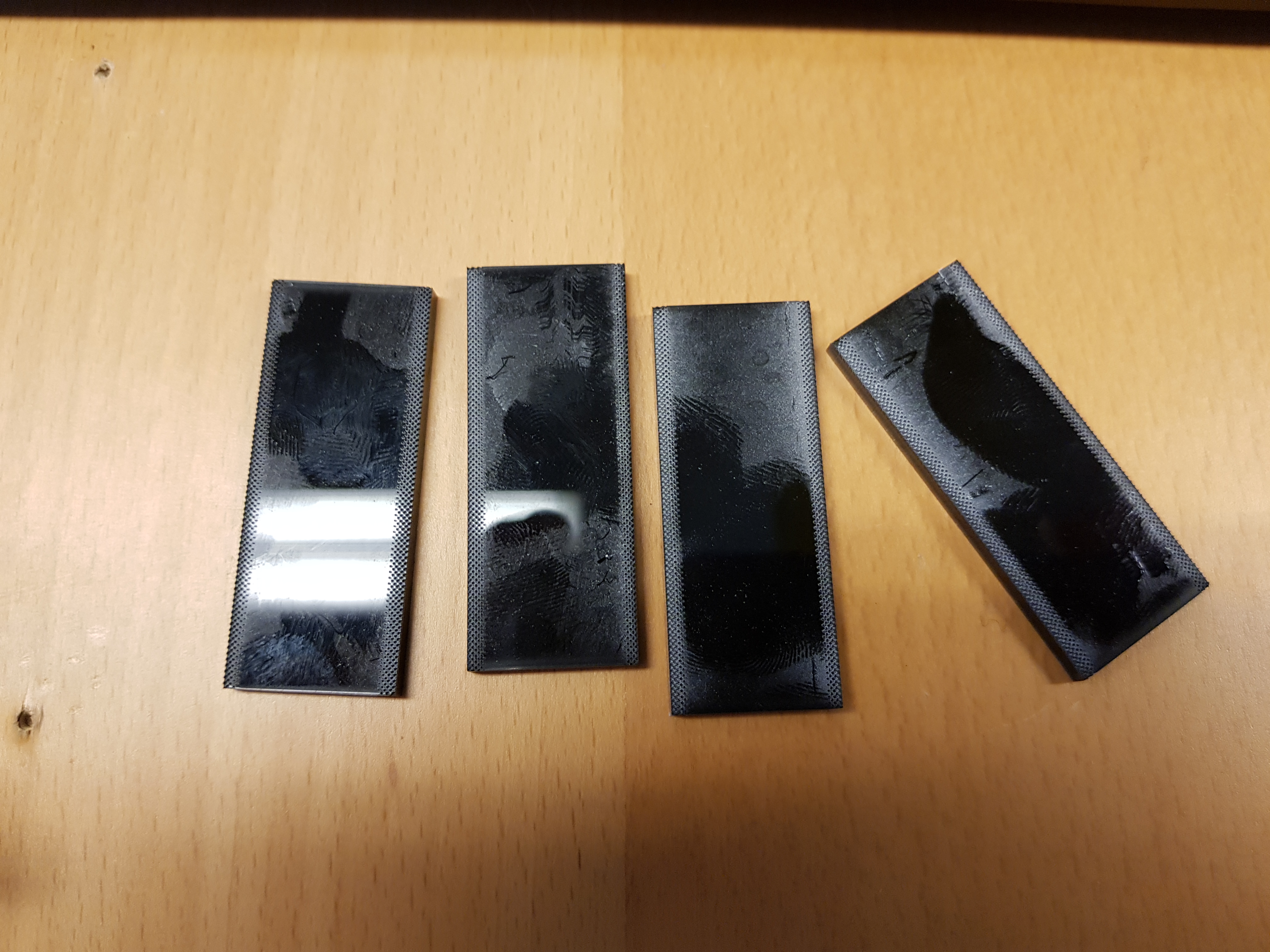
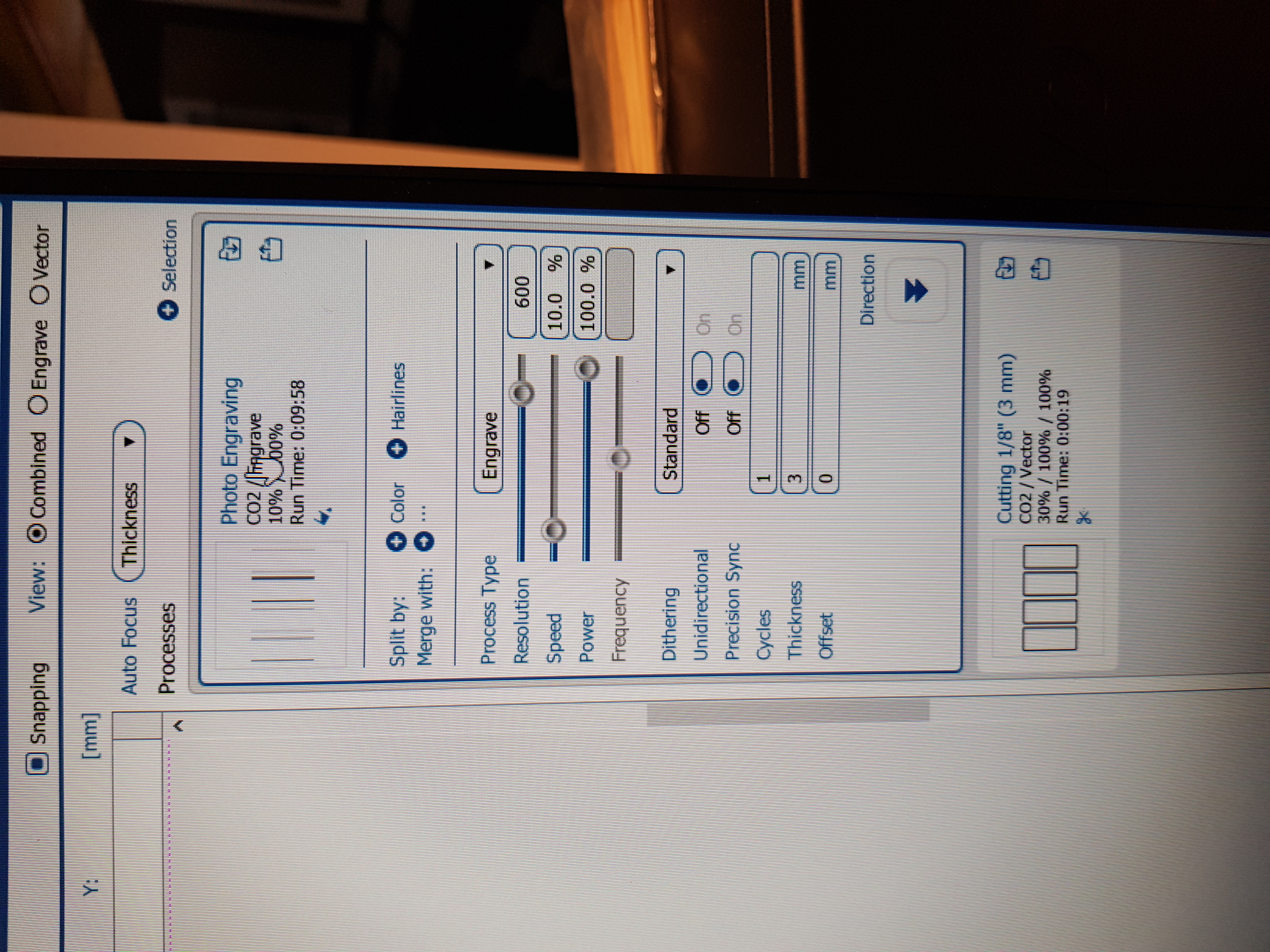
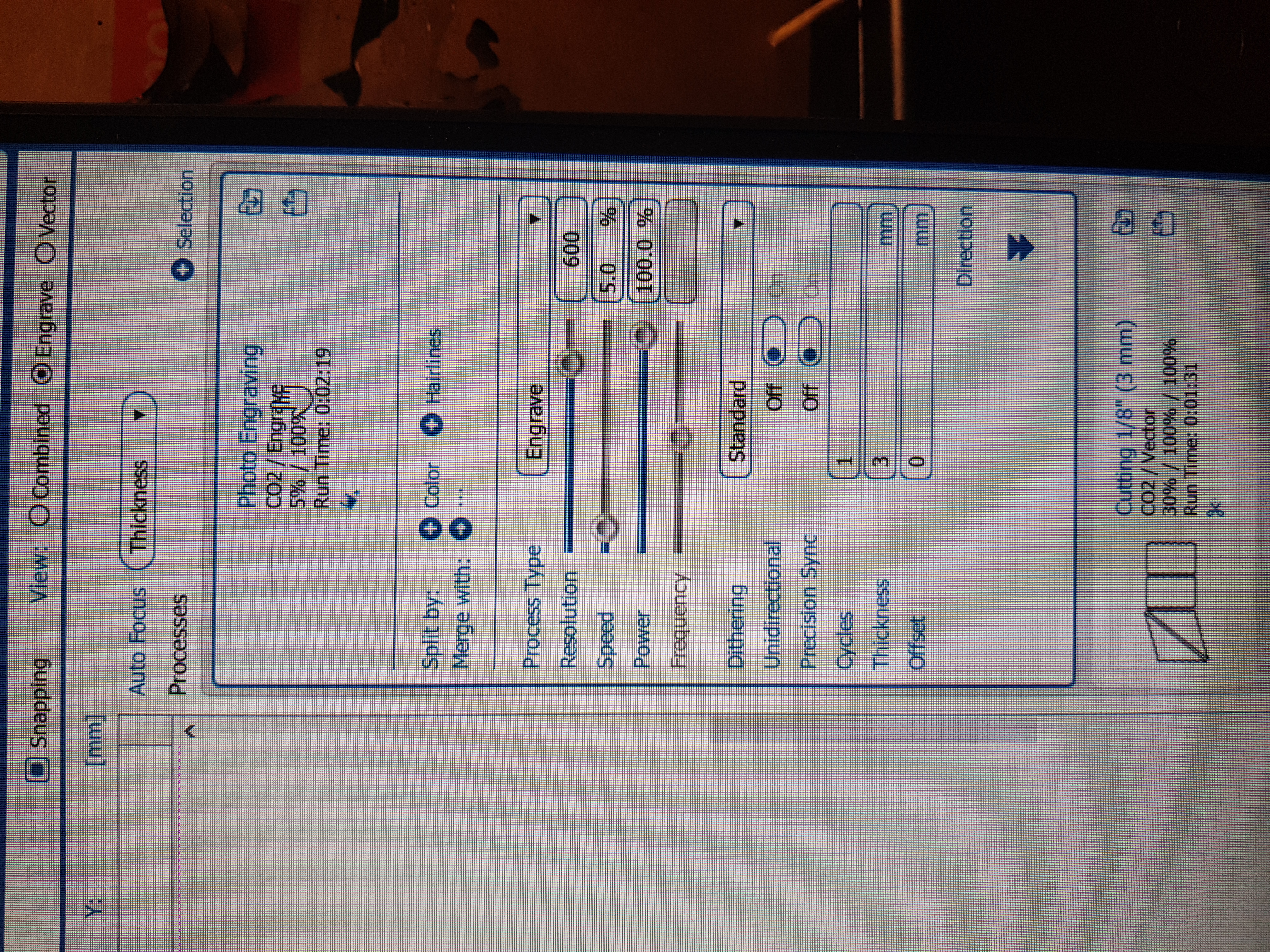
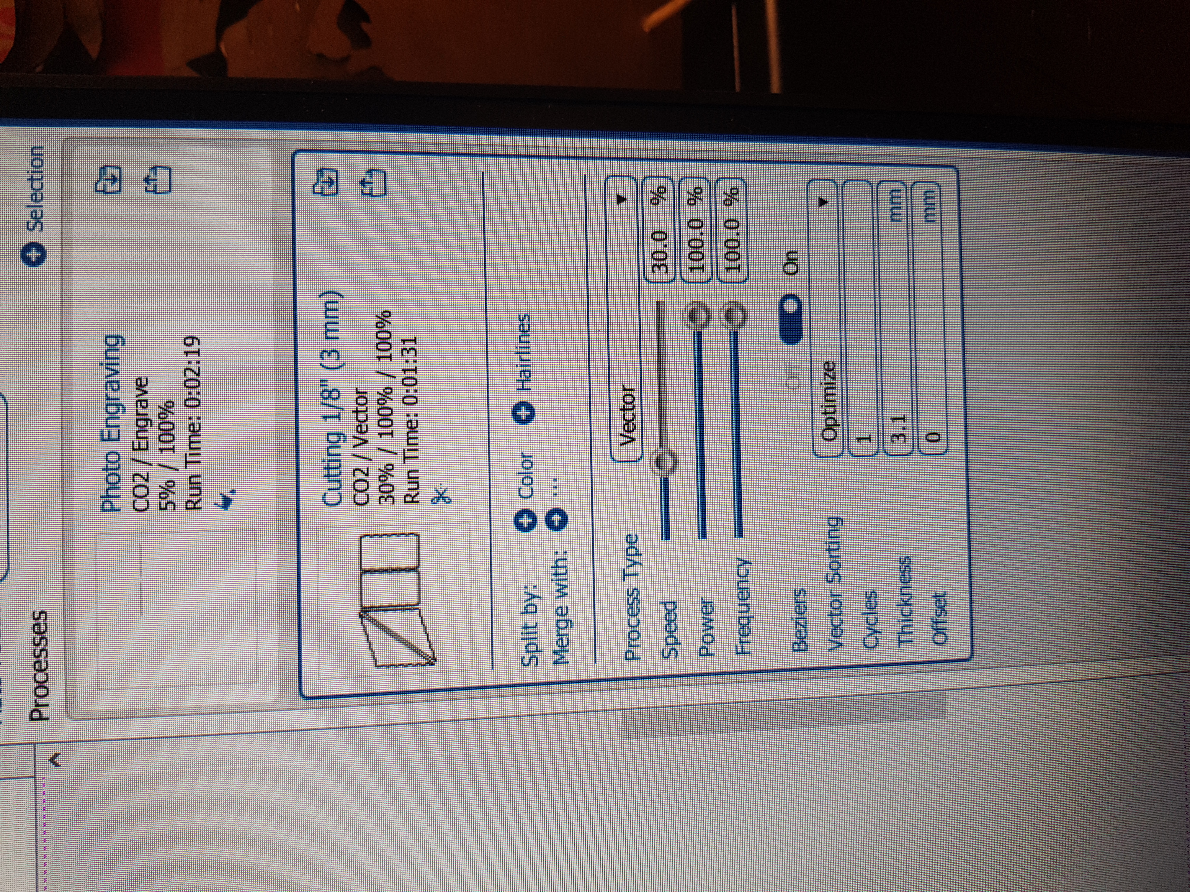
In an effort to make the slope at least noticible, I increased the resolution from 300 to 600, lowered the speed from 30% to 10% and kept the power at 100%. Then I made the lasercutter cut again. Test 2 was much better, I clearly had some slopes, but they were neither steep enough nor with good enough finish.
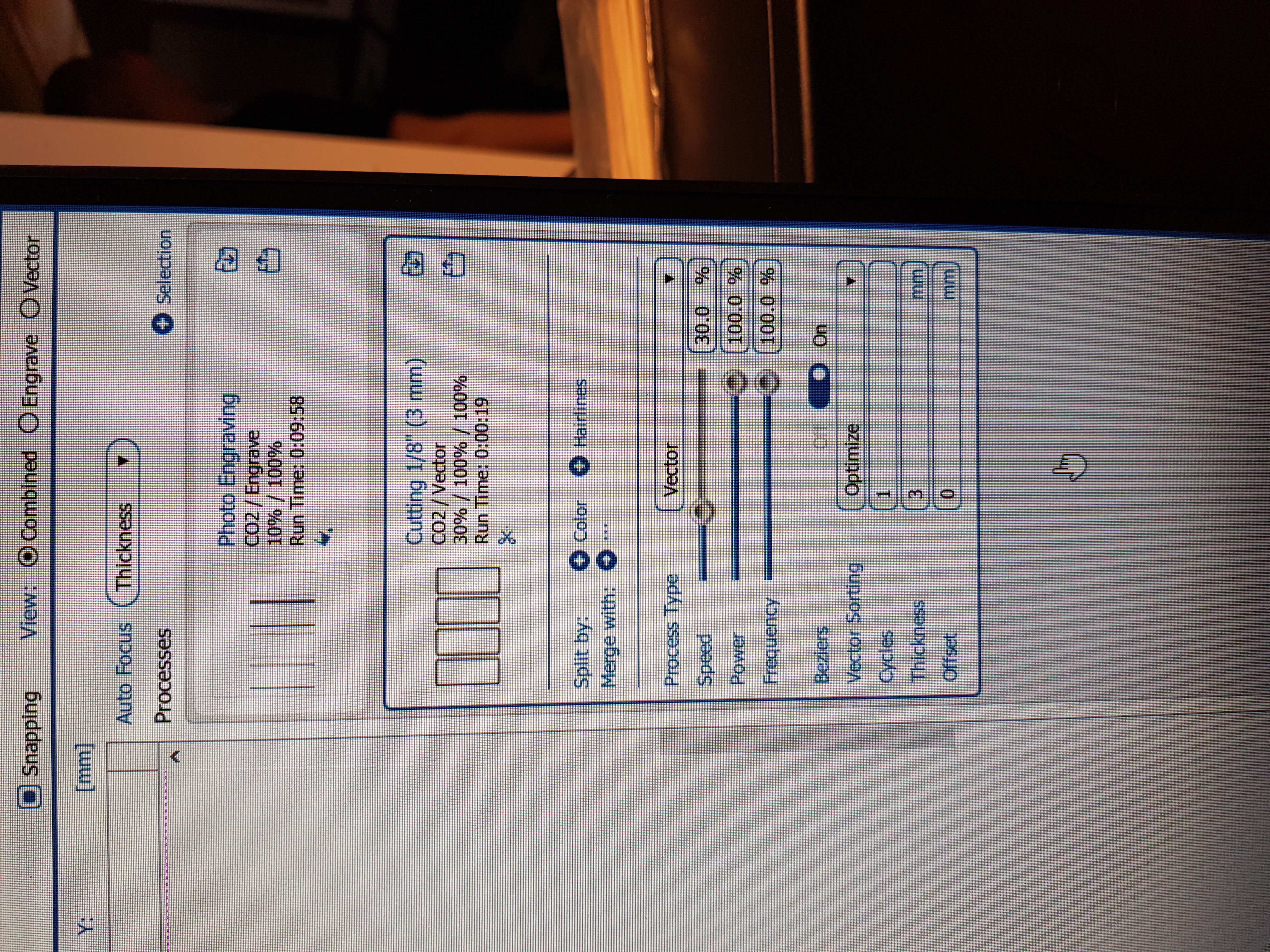
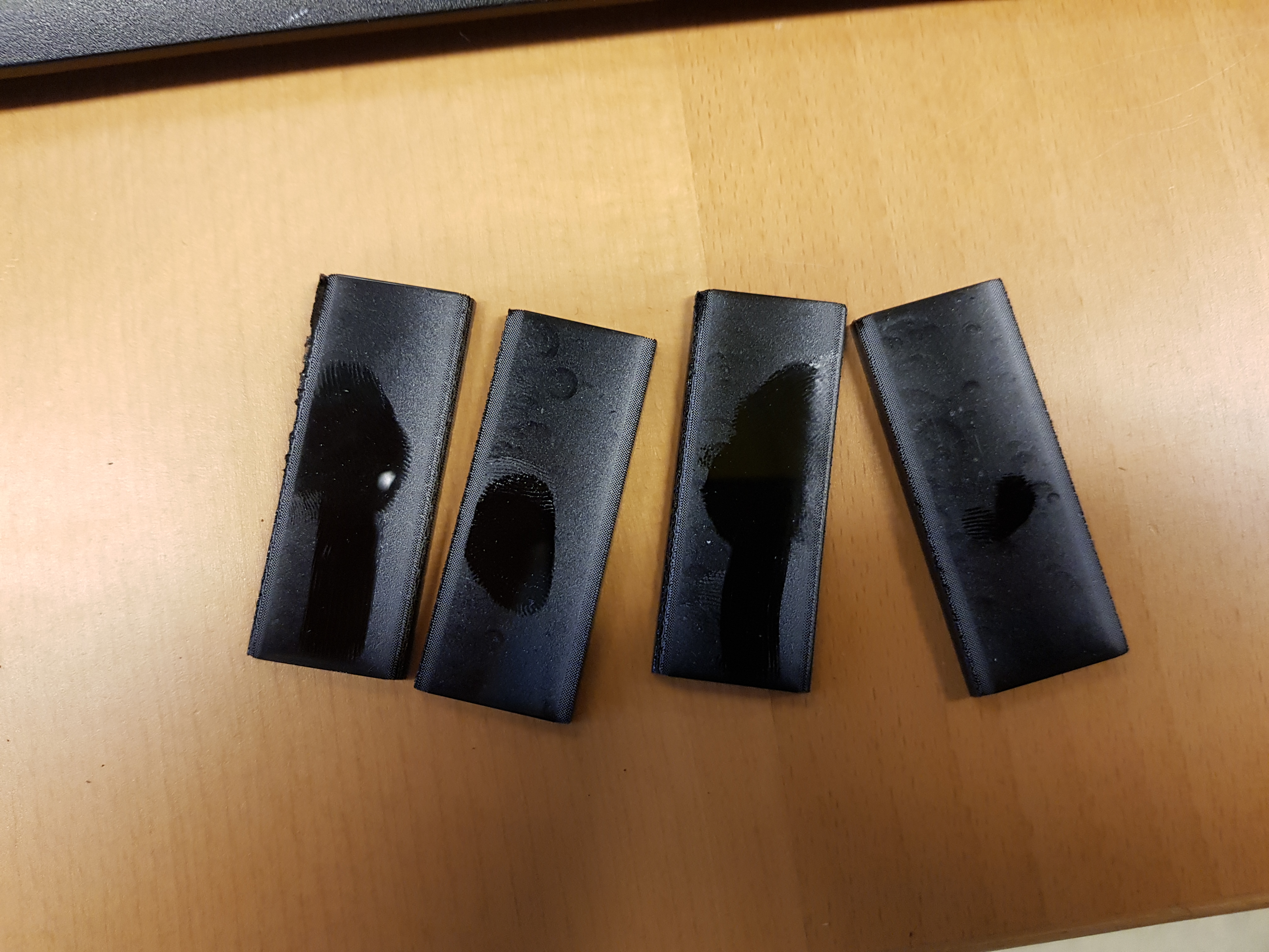
Test 3 was the final slope test and a huge success. It proved that creating a corner with engraving is truly possible. The only change from test 2 to 3 was the speed. In test 3, the speed was only 5%.
Worktime: 4 hours.
Changing the base design
At that point, I knew the slopes would work, but I had to tweak the design of the base a little bit. I drew a bowl holder and a fan holder. In both cases I drew some waypoints and used the spline function. And of course, I used parametric design as always. Additionally, I changed the opening at the top to accomodate for the intended Lego-gearbox, that was supposed to pass through. All those changes were much easier due to using parametric design.
Worktime: 3 hours.
Testing a corner and a logo
I did not want to waste a whole sheet of plexiglass, not knowing how things fitted. Therefore I tried cutting one corner from the base, and thank god I did that. The test was not a success. The lasercutter did not cut all the intended cutting lines and left some of them out. The problem was that in order to get the epilog program to render a cutting line as such, the line has to be on top of all .png files. At the time, I did not know that and I spent a lot of time searching for the solution to the problem. When I finally figured that out, I tried cutting the corner from the same sheet at the same place. The laser went through but as expected, the pressfit was not good. I figured that was due to the laser cutting most of the lines twice. During that test, I also tested cutting a logo. I created the logo using Brandmark.io. But I did not pay for use of the logo, but due to this only beeing a school project with absolutely no intend to continue with, I figured using the logo this time would be ok. Brandmark ownes all rights to the logo. I have purchased logos from them in the past and I really recommend their service.
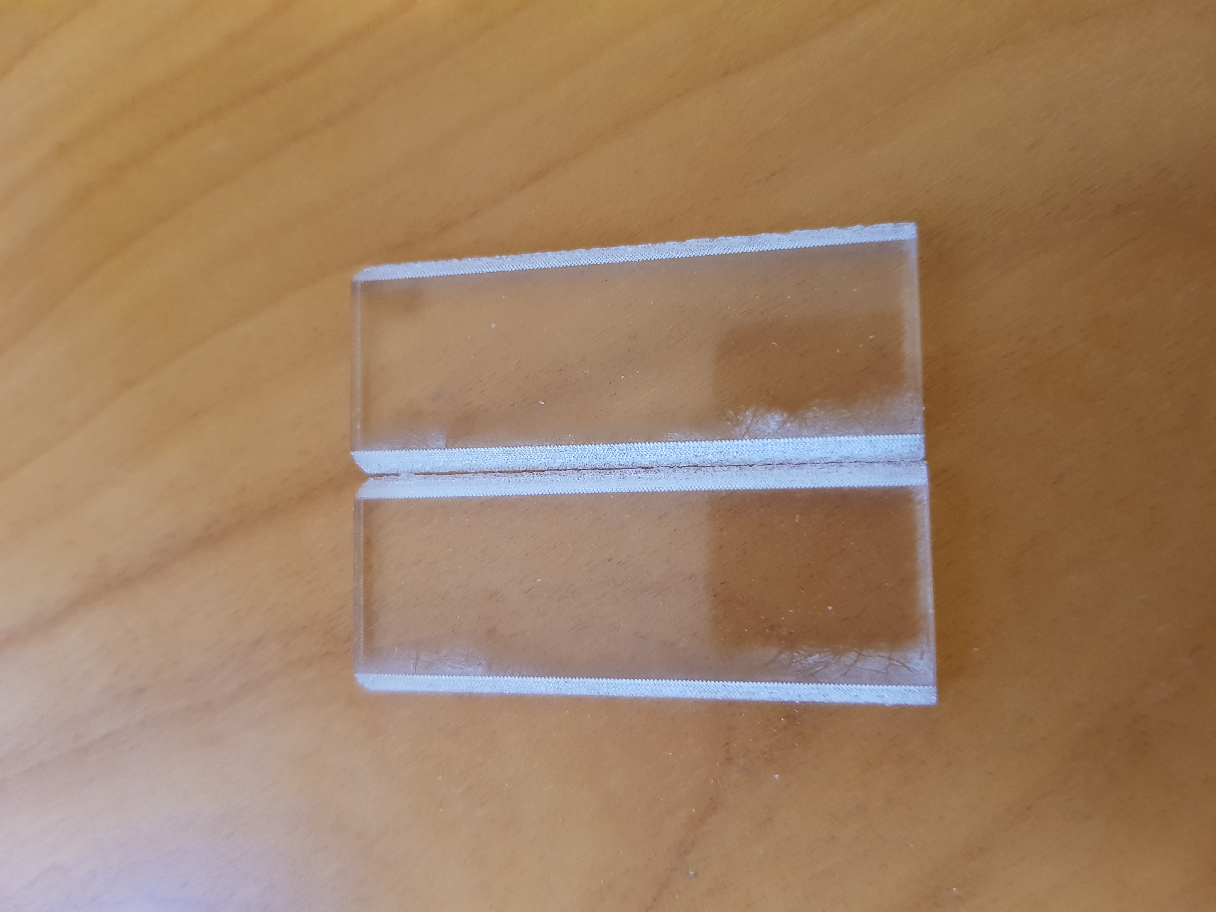
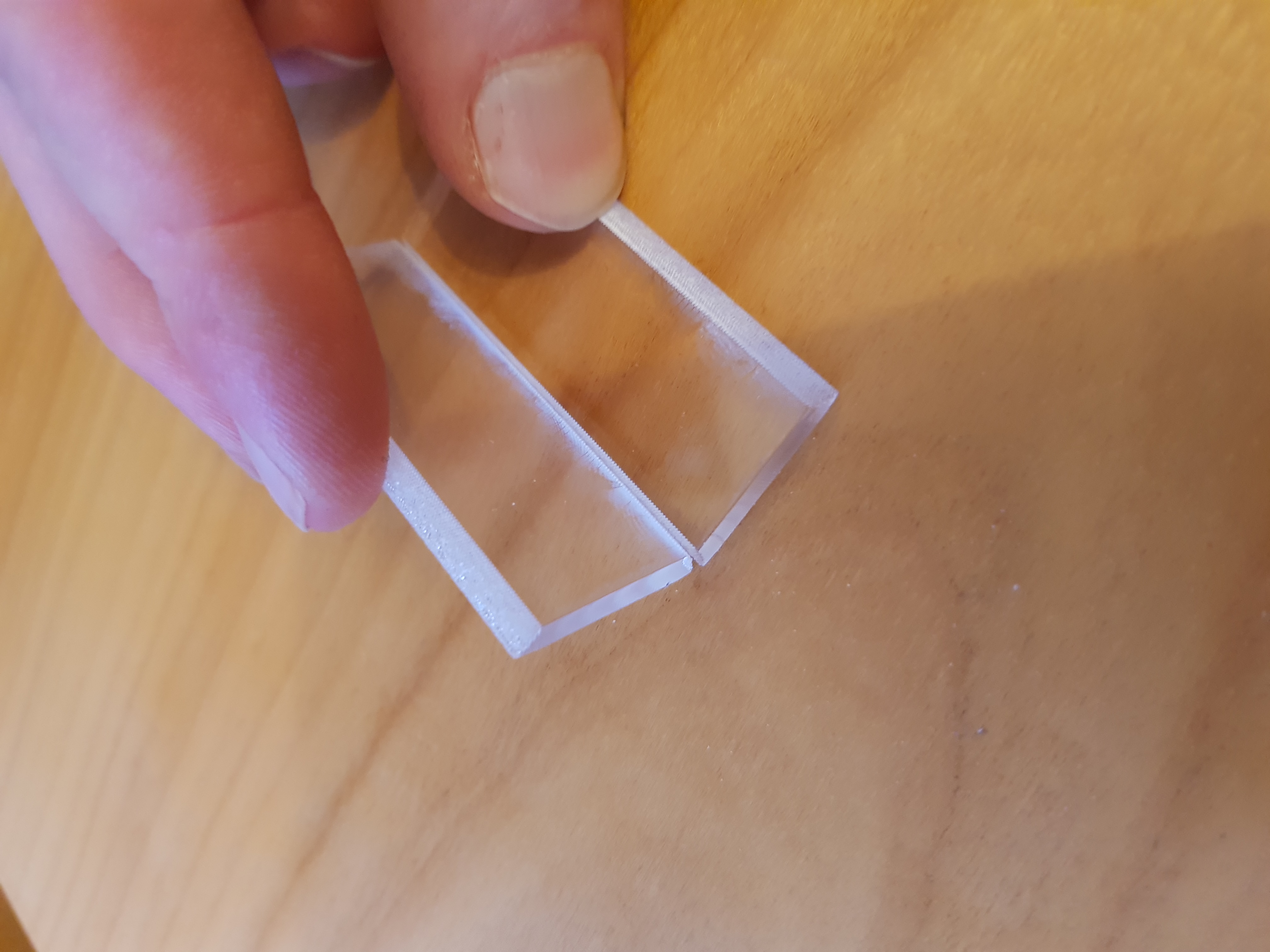
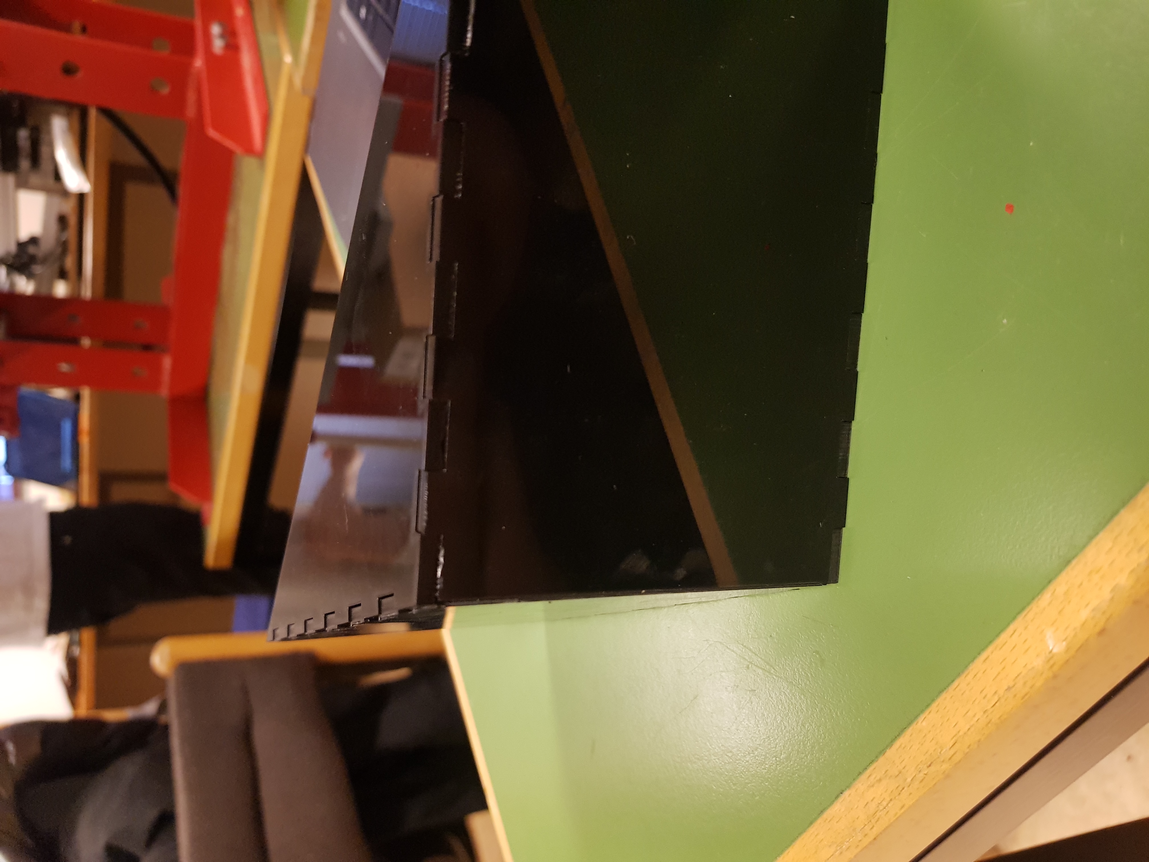
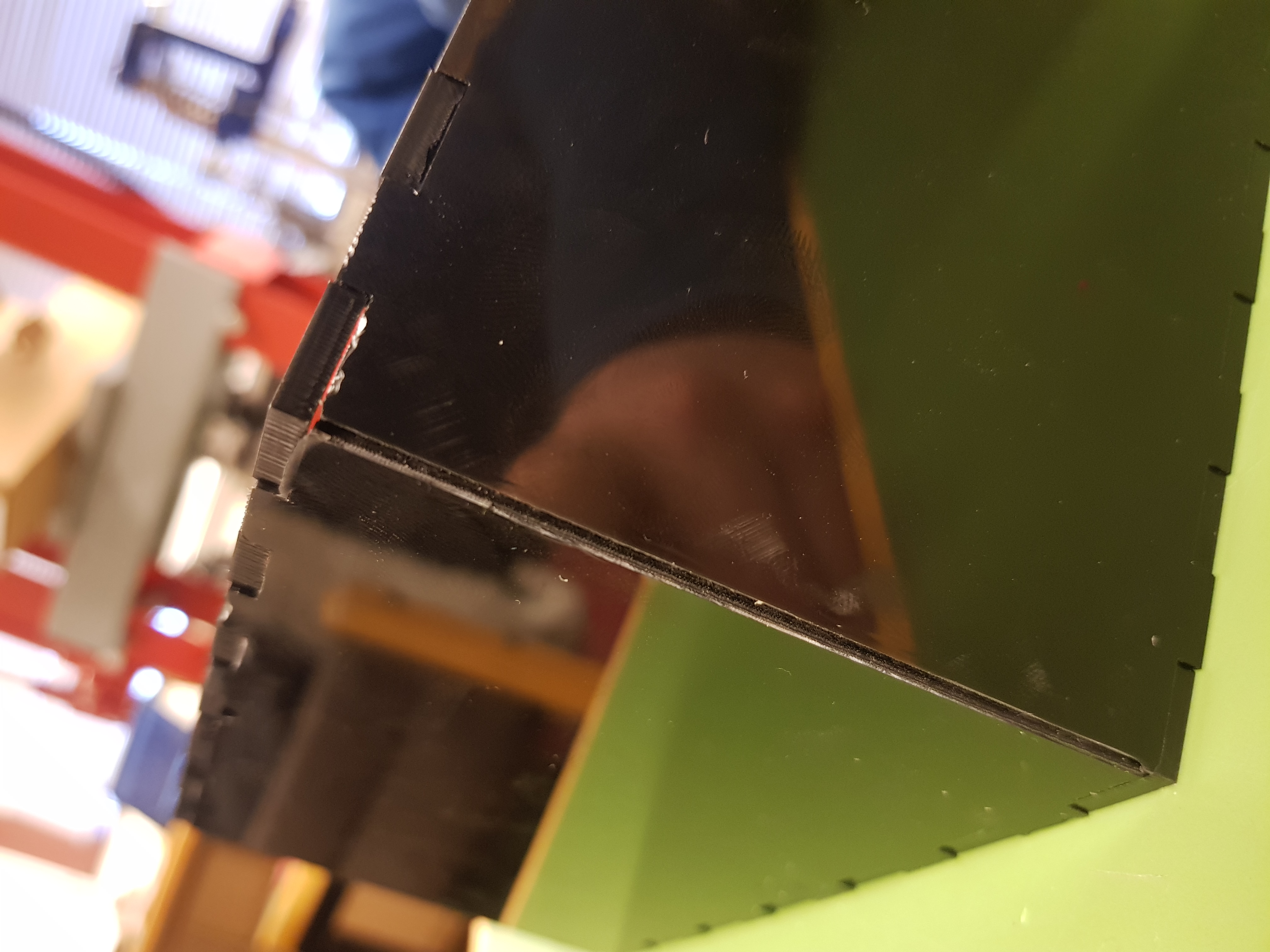
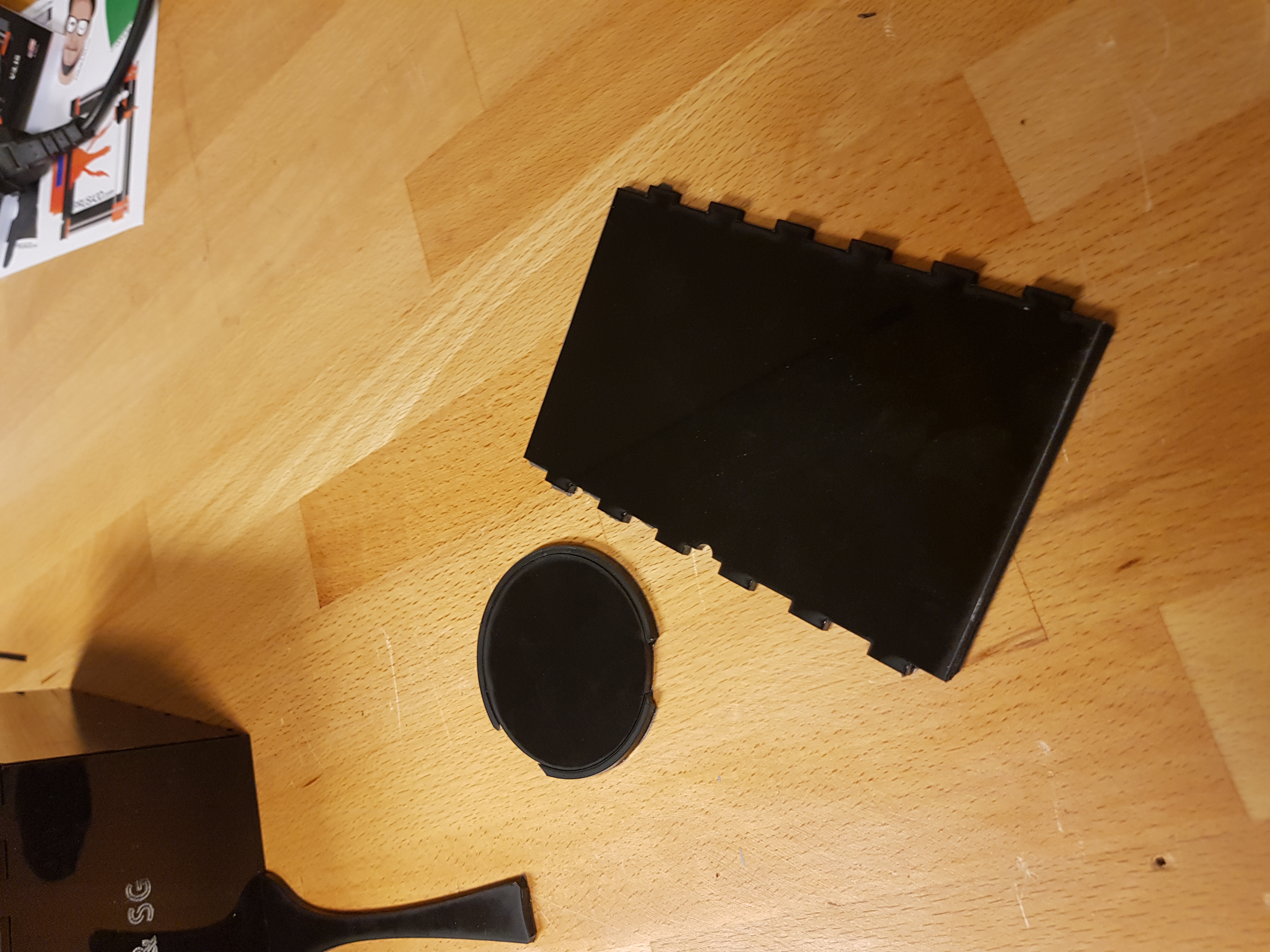
The final test for the laser cutter was to try the corner again. This time I used the black plexiglass, like I planned on using in the base. The test was a success. The pressfit was perfect and the corner aligned just right.
Worktime: 2 hours.
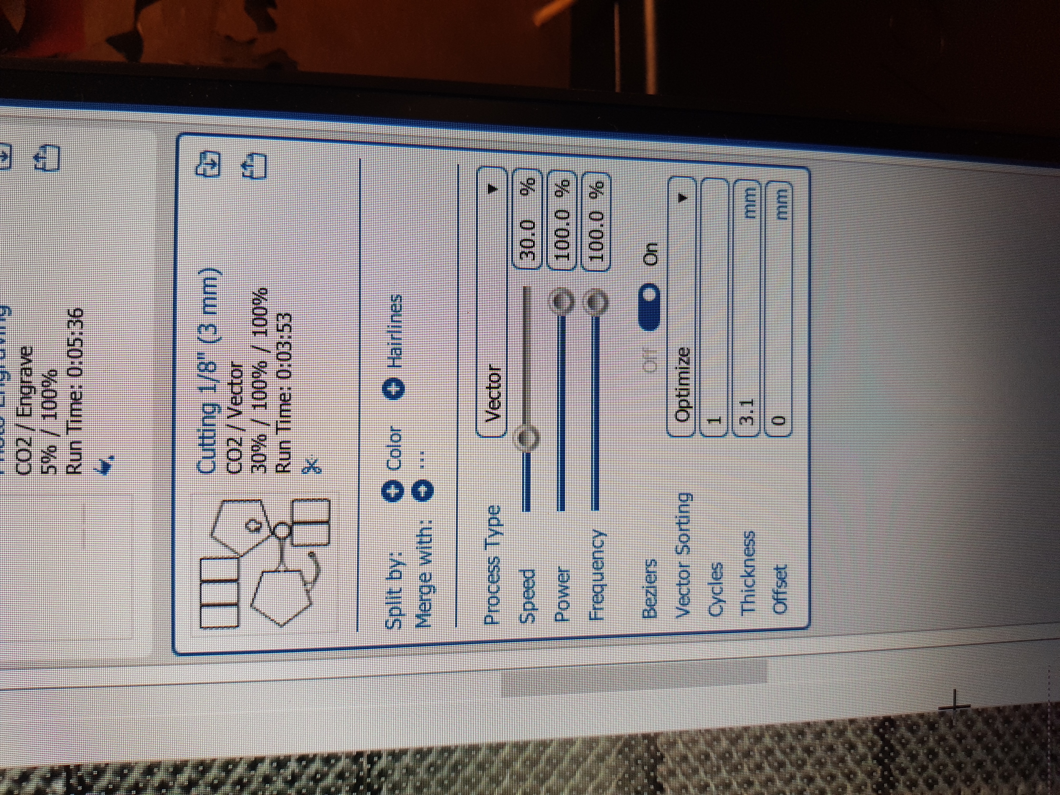
The final cut
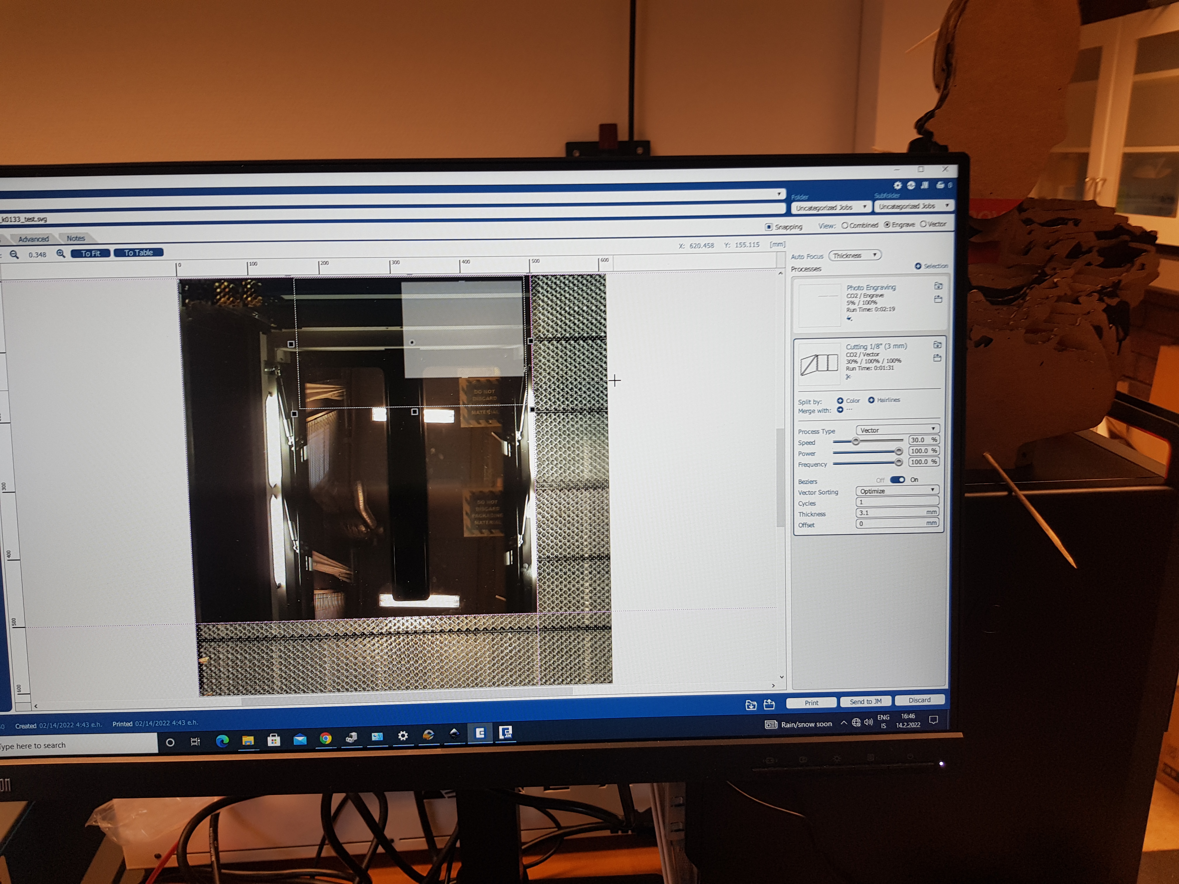
Before cutting the whole base, Hafliði reccomended me to read the manual for the machine first. That was to make sure, the cutter could withstand engraving at full power for such a long time (The cutting of the tests was taking about 10 minutes). I found the manual on Epilog's website and read it quickly. The manual did not mention any constraints of using the device for longer periods of time. There was one thing though that cought my eye. Engraving in landscape relative to the lasercutter is much quicker than in portrait. To reduce time significantly, I rotated the Inkscape drawing and started cutting.
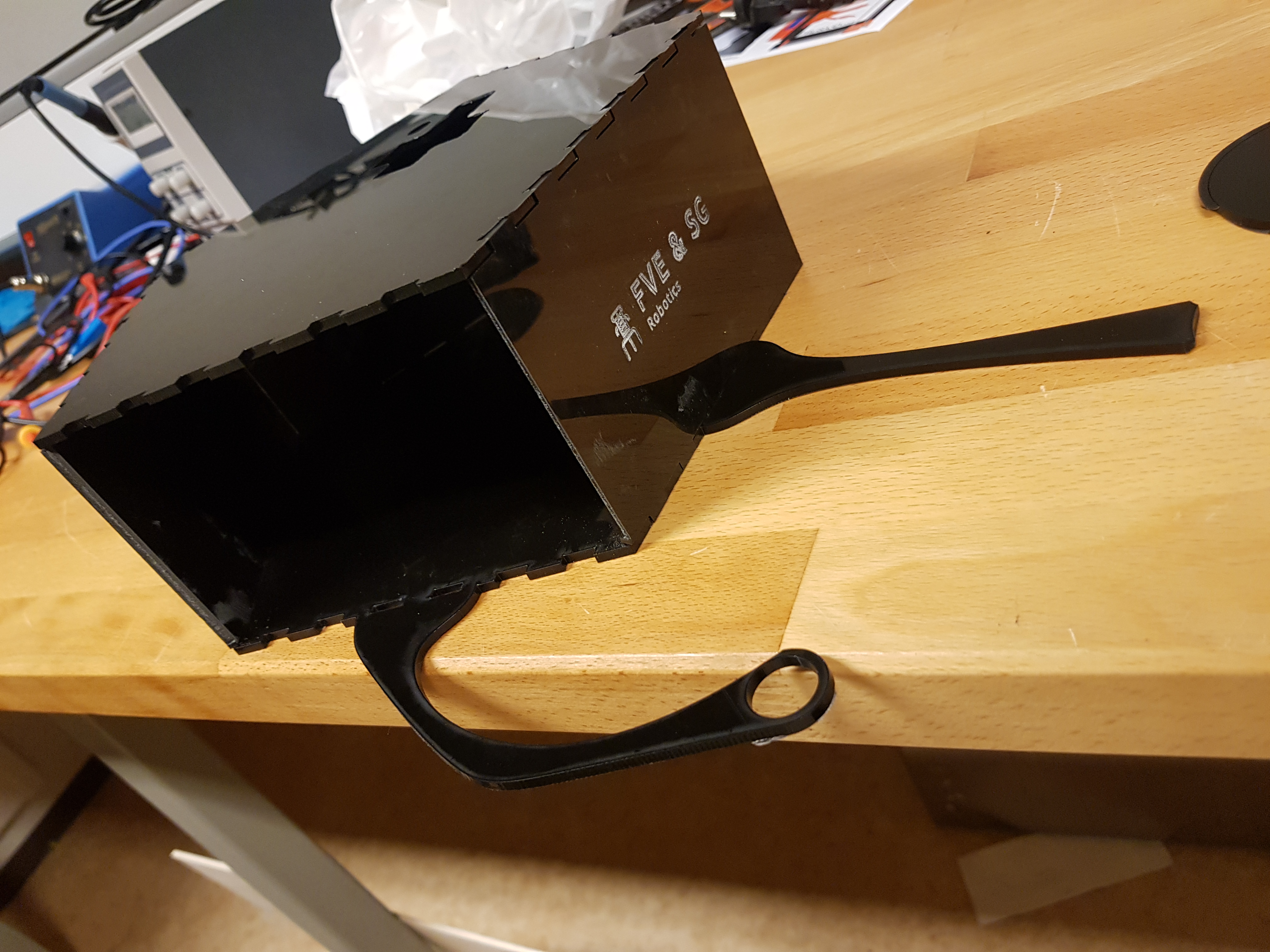
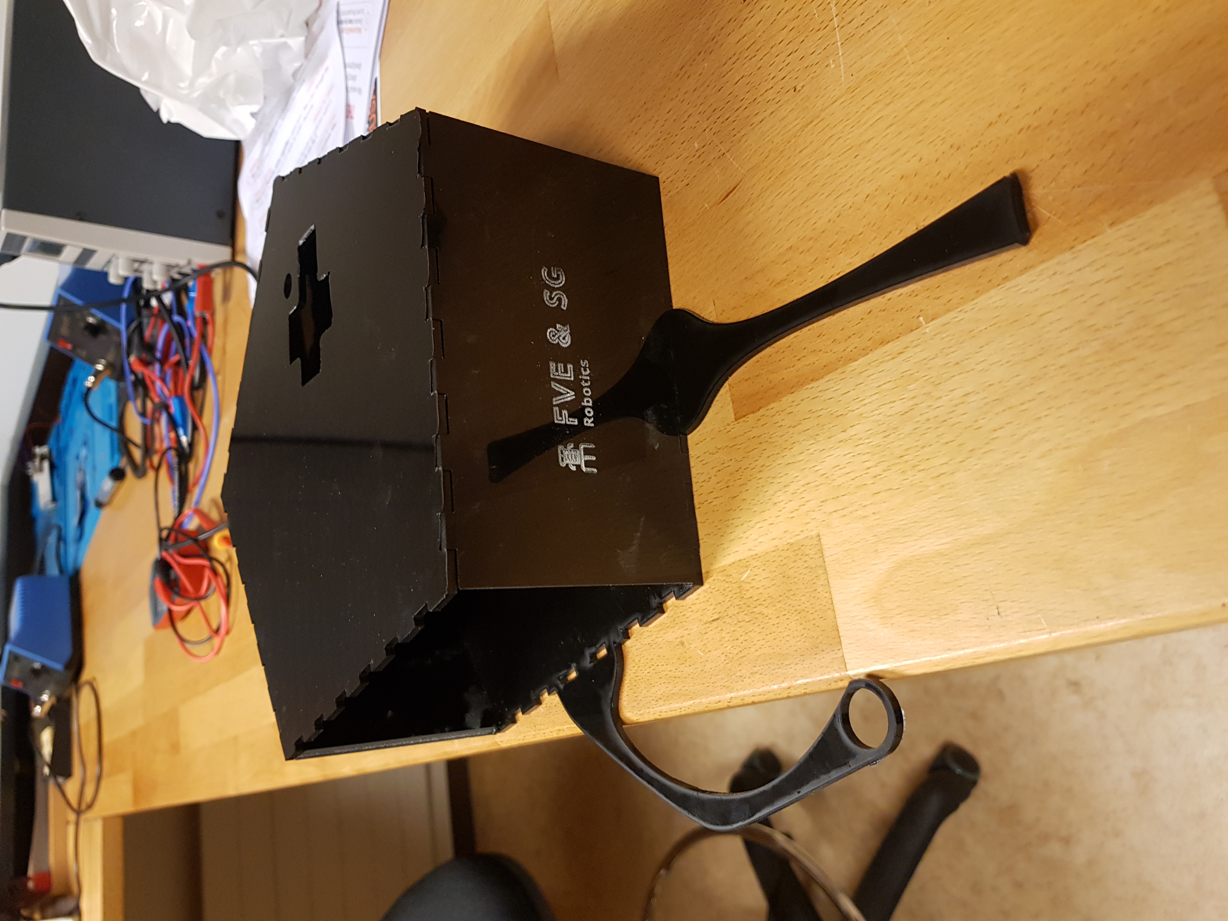
The cutting was a success for the most part. The ring at the tip of the bowl holder failed along with one side of the base. Those fails were due to two factors: After cutting the base, I measured the thickness of the material to be 3.15mm not 3.0mm as expected (Note to self: Measure your material before working with it) and probably some misalignment in the flat bed of the laser cutter. The fail in the fabrication was that the laser did not cut through in the right bottom part of the sheet, resulting in a broken bowl holder and a failed side. Luckily, I had an extra side from the corner test, which I used and the circle for the bowl turned out to be unnecessary for the robot to work properly.
Worktime: 4.5 hours.
Total worktime: 26.6 hours.
Total worktime for project 2
- Part 1: 6.25 hours
- Part 2: 26.6 hours
- Documentation: 10.75 hours