3D printing and scanning
Project 3 in Computer Aided Fabrication
Intro
Project 3 was made up of two parts:
Part 1:
3D scanning an object of my choice using any program/app available.
Part 2:
Designing and 3D printing an object that can not be made using a 3-axis CNC machine using parametric design.
Used material was not to exceed 100g of plastic.
Desicisions such as amount and placement of support material, material choice and overall design, had to be made based on tests and research.
Available materials were e.g. PLA, ABS and PETG.
Part 1 - 3D scanning
I started by installed three best rated free 3D scanners according to App Store.
I downloaded 3d Scanner App, ScandyPro and Sakura3D SCAN.
Upon opening 3d Scanner App and Sakura3D SCAN, I was informed that my device was not compatible with the apps.


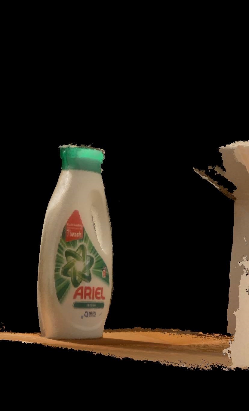
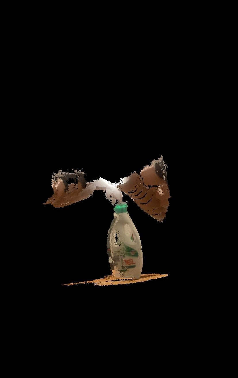
The apps require LIDAR capable devices such as iPad Pro or iPhone 12 Pro, which I do not posess. I did a further search of apps because I wanted to try more than one app for a broader comparison. I looked up some rankings online from All3DP and CellularNews.com. Keywords: "Top 3D scanner apps", "3D scanner app", "iOS compatible 3D scanner app". I did not find any additional apps on those sites, which worked on my device and were free. The only app that actually worked was ScandyPro, but the results were not great. It came with it's restrictions. I could e.g. only use the front facing camera on the device, I could not save scans without paying additionally for that and scanning small objects was not possible. I stared off by scanning a detergent bottle and the results were following:
Scan 1:

In the scan, I tried taking a photo head on the object. The results were bad to say the least.
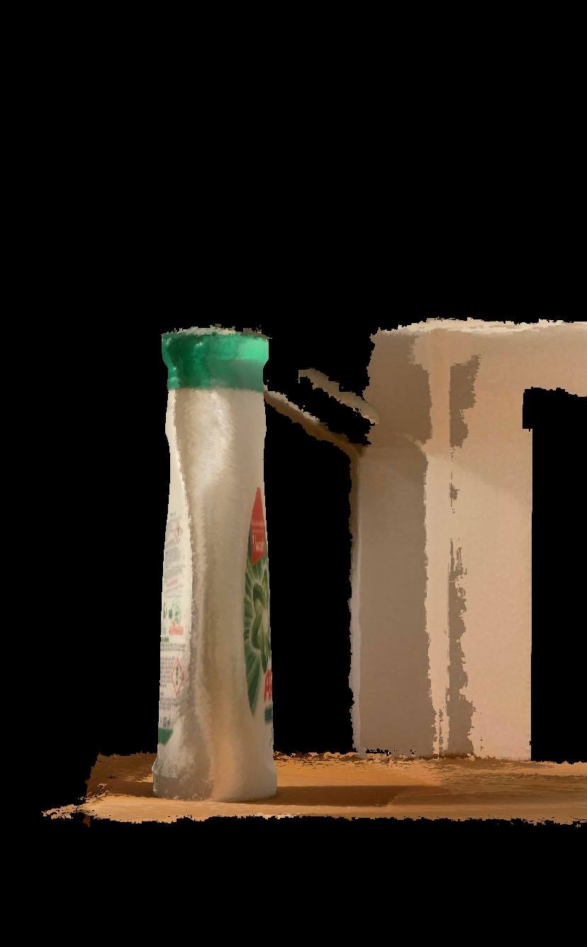
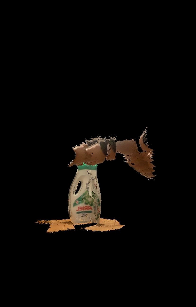
In scan 2, I tried moving around the object in an even radius. It was hard keeping the device steady and pointing in the right direction using the front facing camera, due to lack of visibility on the screen:
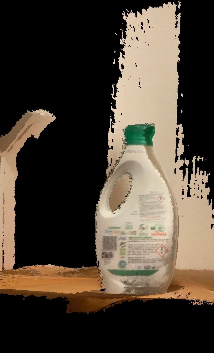
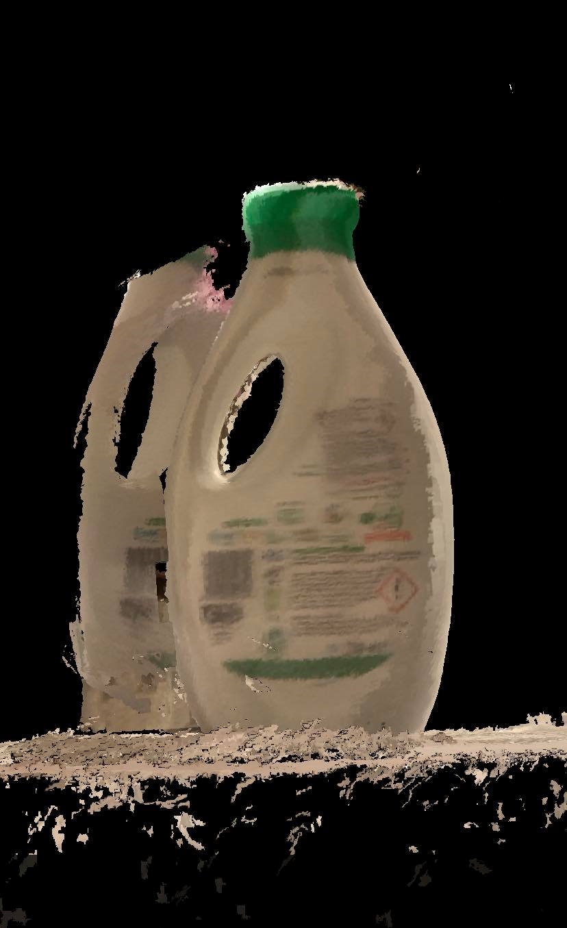
The next thing I tried, was to rotate the object with my hands. The results were only worse:

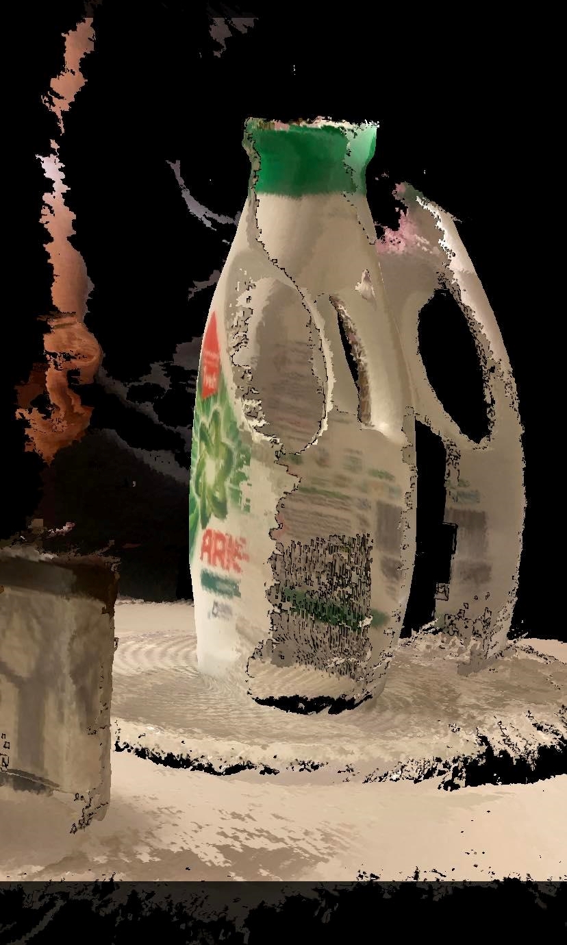
The last thing I tried with the detergent bottle was to put it on a cake plate and rotating the plate itself. Despite all the effort, the results were similar to the last test: terrible.


The next try was to scan a Moomin jar. The images speak for themselves:
I noted that scanning in a busy environment is not as good as in a simpler one.
At last, I tried scanning a Nespresso capsule. That showed the constraints of the app regarding small objects:


When trying to download the 3D scan, I got prompted with this window:

and when trying to download, I got the message that the file was not compatible with my device.
Total worktime: 3.2 hours.
Part 2 - 3D printing
Preparing a print test
The first task of the part was to test the 3D printer. We had access to two Prusa i3 MK3S+ printers, which of one had a MMU2S multi filament add on. Therefore I started by installing the Prusa Slicer on my computer. I have used the slicer Cura in the past, but according to Hafliði the Prusa Slicer was supposed to be more capable. After using the slicer for this project I have to agree.
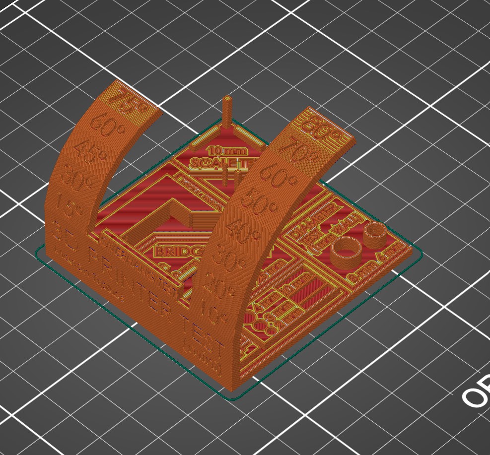
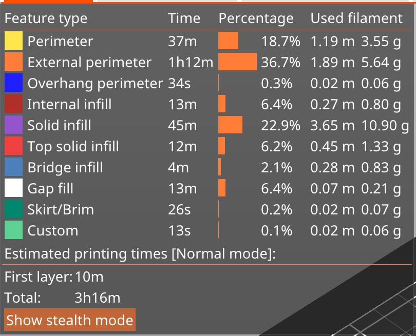
Then I surfed the net, searching for some 3D printer test files. My mind went straight to the Torture Toaster. But upon slicing, I realized that printing the toaster would take approximately 14 hours. That was simply too long. After some more search, I found a great test also on Thingiverse. Unfortunately, that print took around 10 hours to print, which was also too long. At last, I found a print that was perfect for the job.
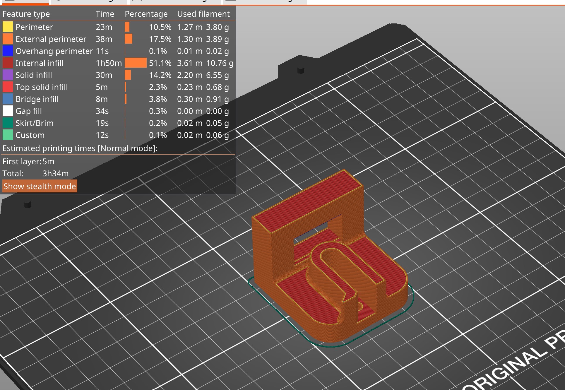
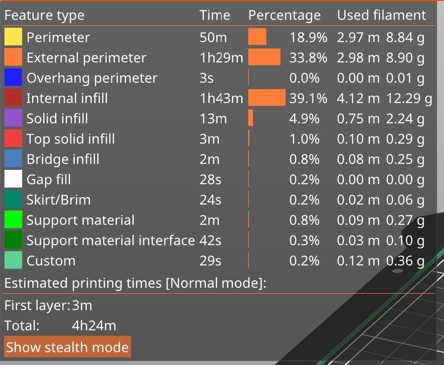
I changed the slicer settings to:
Fill density: 10%; Brim: No brim; Auto generated supports: OFF; Z travel: 0; Solid infill: 0,8
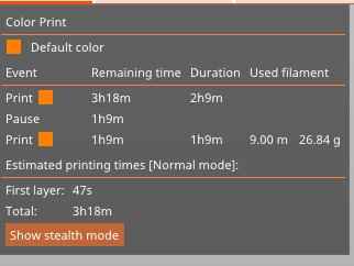
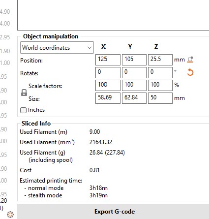
in order to reduce the print time. After changes the print time was only 3 hours and 16 minutes.
Printing the test was a group project, done with Friðrik Valur and Finnur Mauritz. More information can be found at Friðrik's website.
Worktime: 4.4 hours.
Designing inserts
I descided to split my 3D printing project into two parts for the soup robot: An insert for the arm and a duct on a pillar for a fan. I started by designing an insert around a T-shaped Lego brick, that would pressfit to the arm of the robot. All dimensions were added into the parameter table, which made tweaking the design later on a lot easier. After careful measurements and some calculations I had a design. I showed Friðrik the design, and he had doubts about securing the brick. Therefore I canged the design to a closed one with the intesion to pause the print and insert the brick. The design did not make it all the way to the printer though.
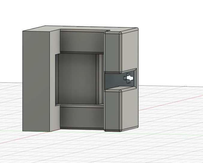
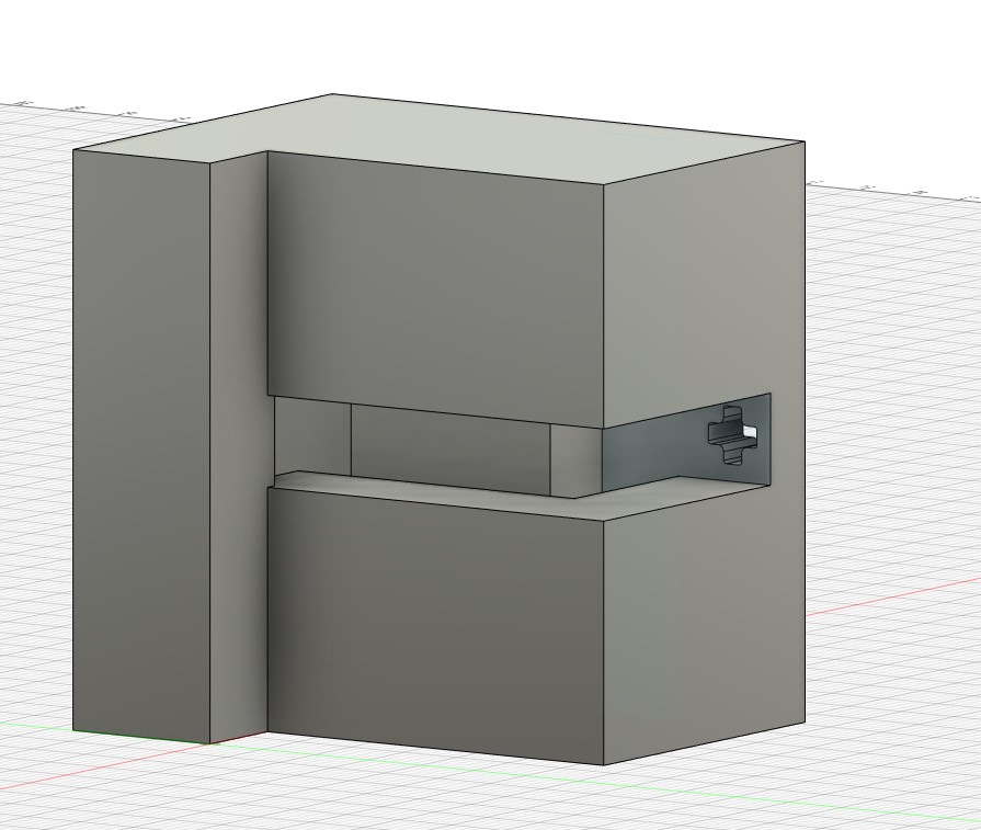
In the design process for the soup robot, we descided to change to a slightly bent lego brick, instead of the T-shaped one. To create a nice pressfit and to place the holes for bolts in the right places, I downloaded a CAD file of the lego brick as a mesh and drew around it. I of course measured an actual brick and compared it to the drawing using the Inspect tool in Fusion. I used this website to find the excact color of Prusa-orange filament to change the apearance in Fusion 360.
Worktime: 8 hours.
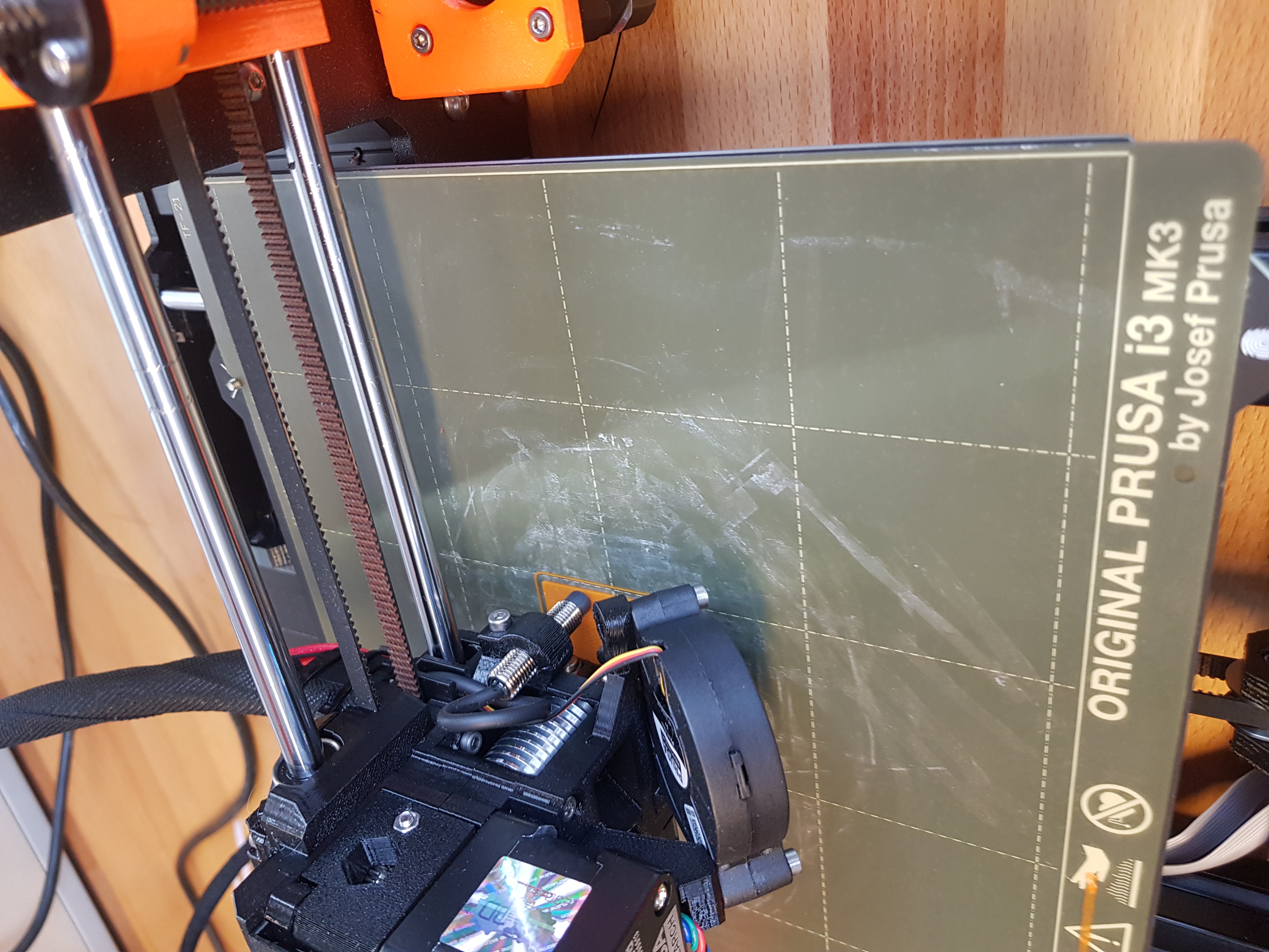
Printing the insert
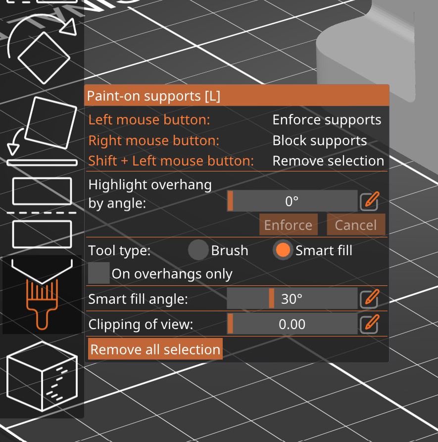
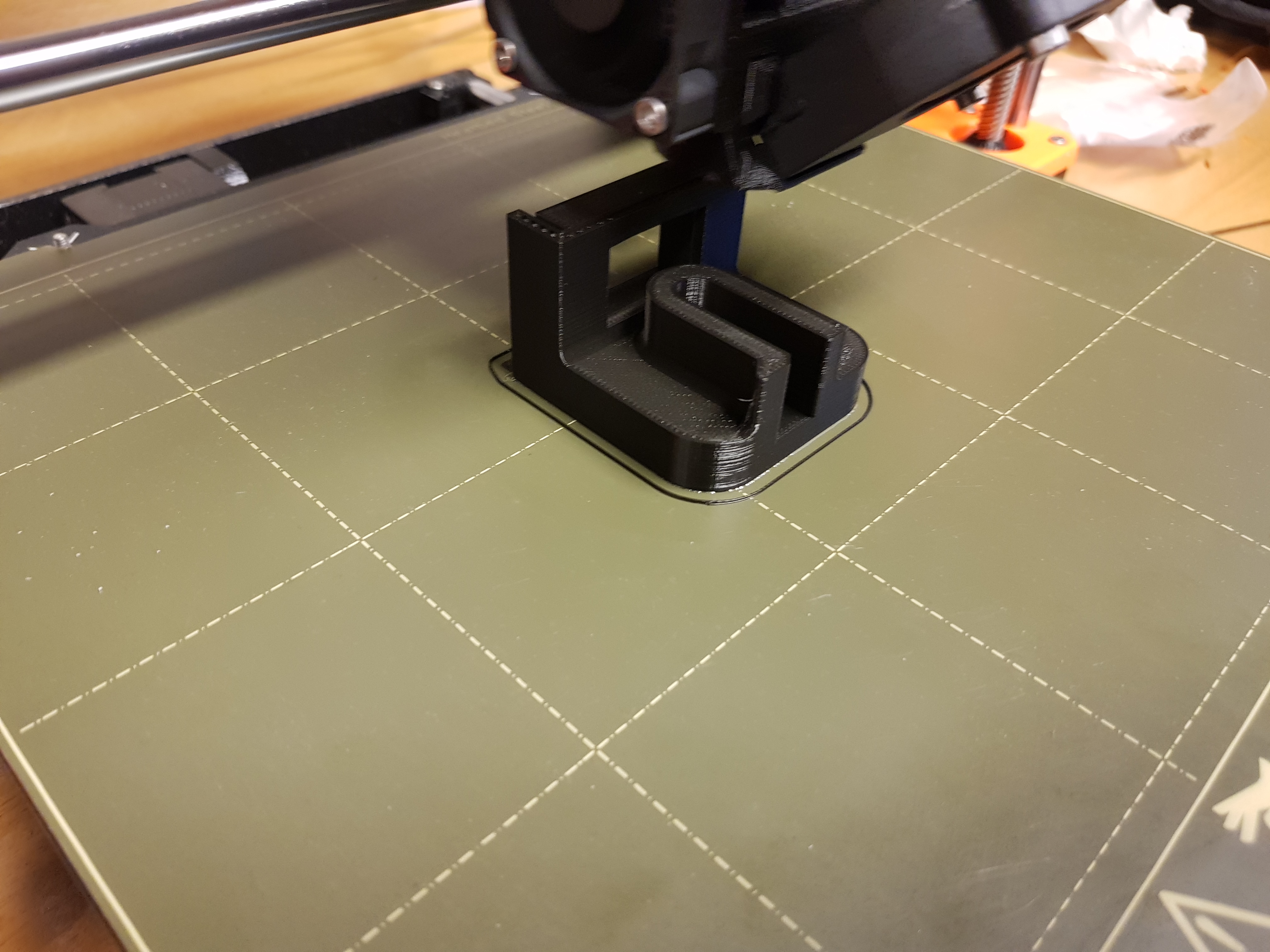
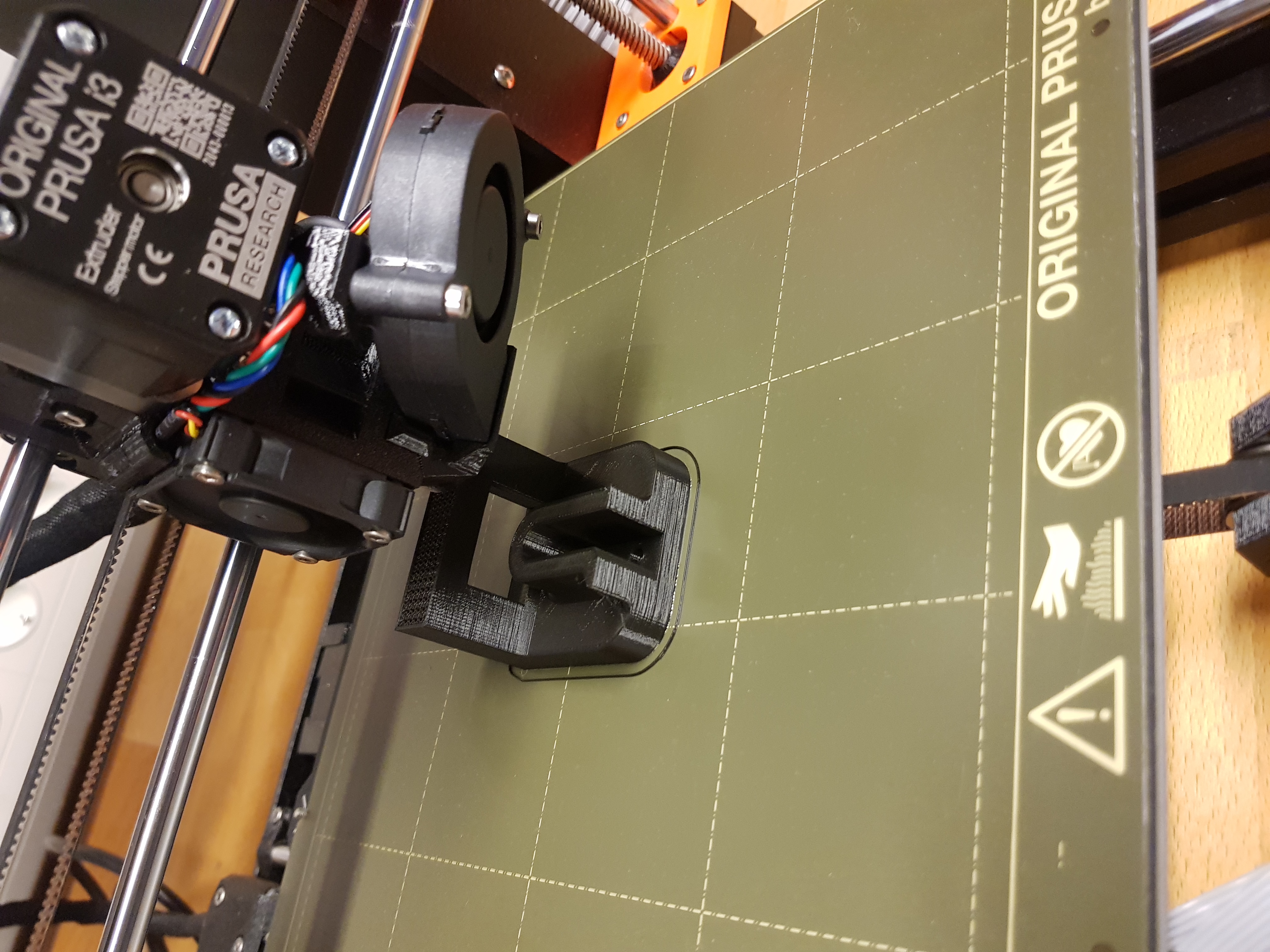
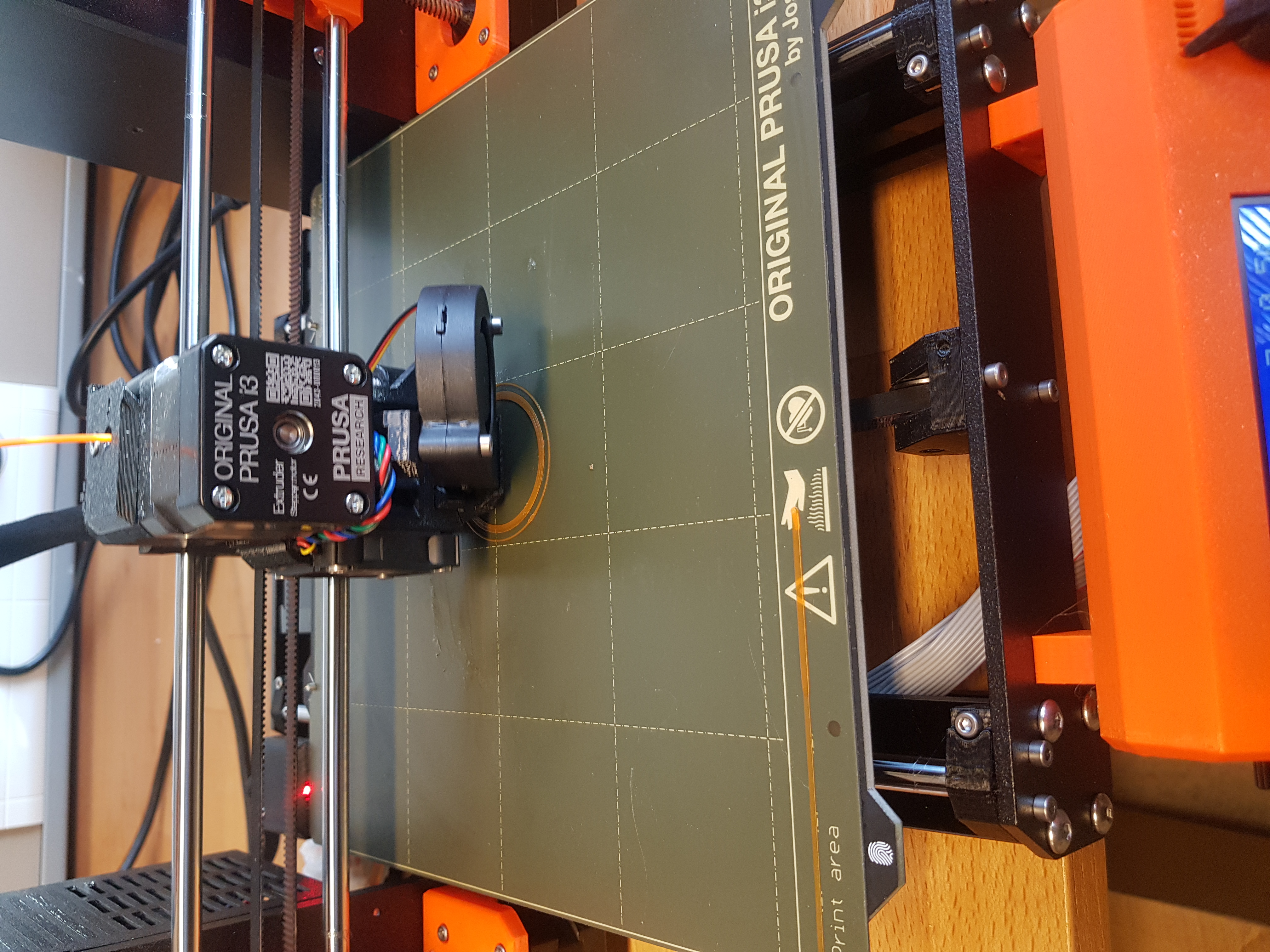
When I got to the FabLab, I downloaded the .gcode file from the slicer to a SD card and inserted it to the printer, made shure the printer settings were adjusted for PLA and started printing. The print had not gotten very far when I realized, I had forgot to add support material. Therefore, I stopped the print and went back to the slicer to add support. I used the smart fill tool in the slicer and selected the only surface I thought needed support material. I was certain that the printer could bridge 35 mm based on it bridging exceptionally well for 25 mm which was the maximum bridging tested in the printer test. That also turned out to be a mistake, but not a serious one and it was fixed with a file in the end. Due to asthetics for the robot, I switched printers between the supportless fail and the actual print, resulting in the insert beeing black instead of orange. To accomodate for that, I had to slice the part again for the other printer. That was no problem and not time consuming.
.jpg)
.jpg)
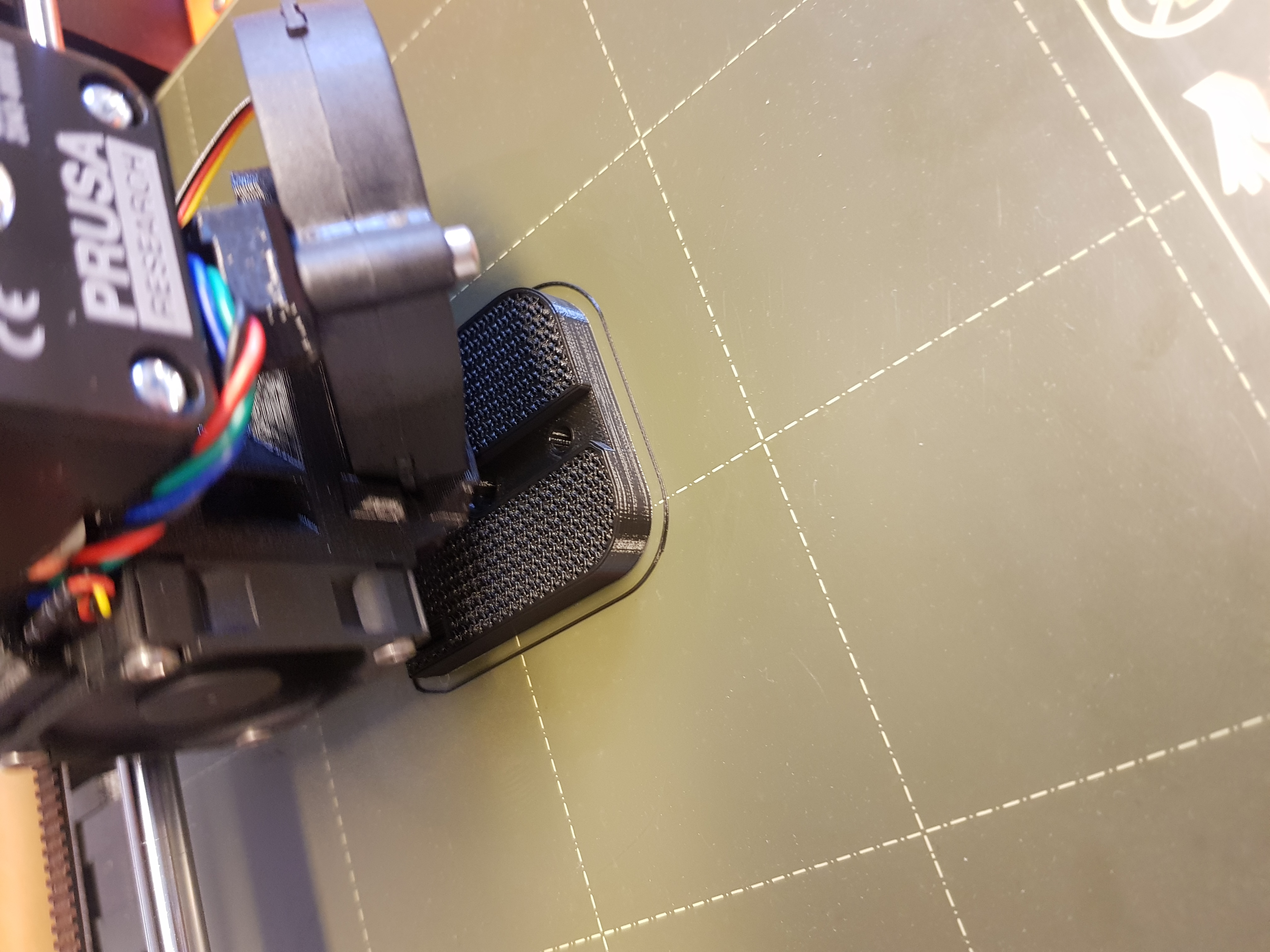
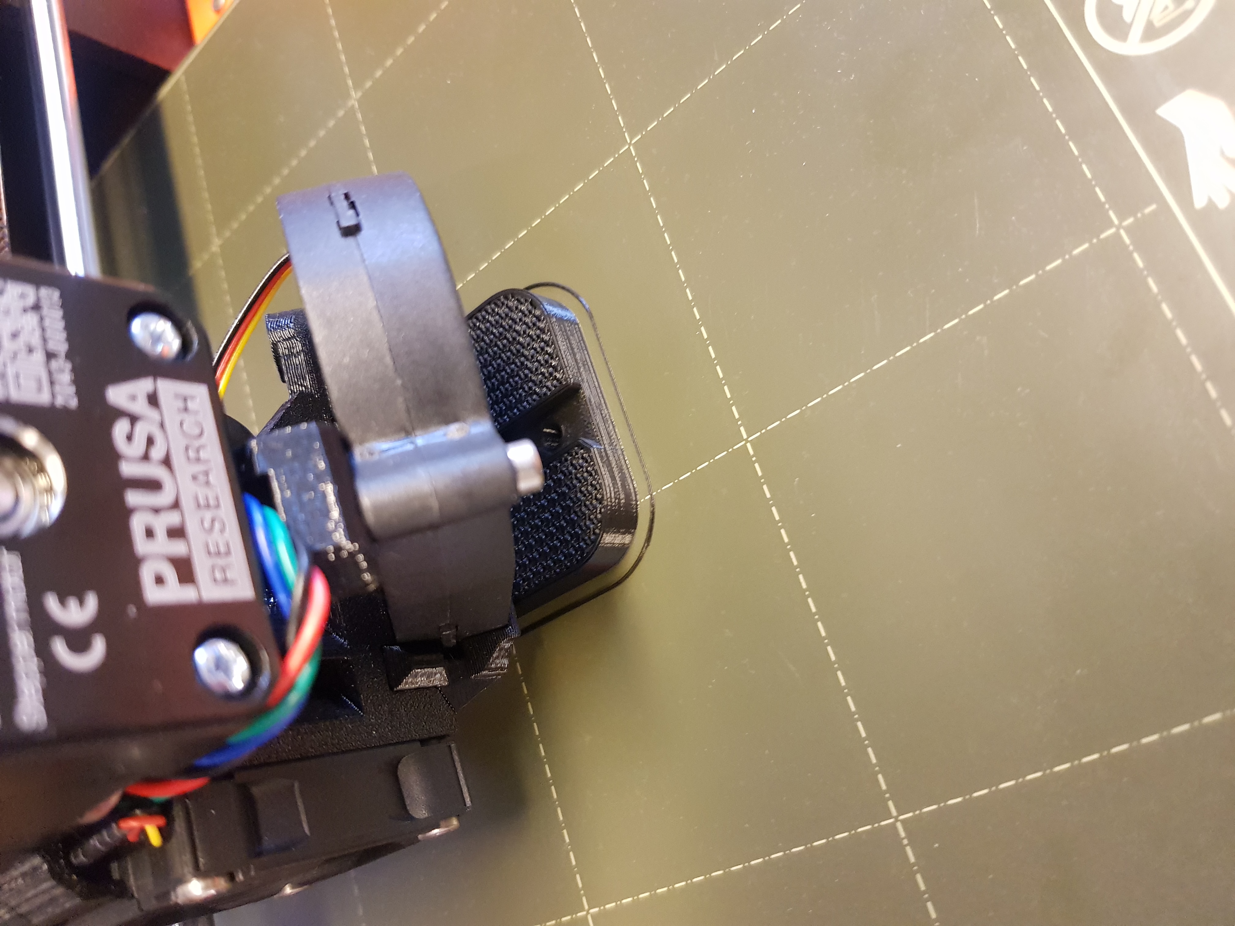
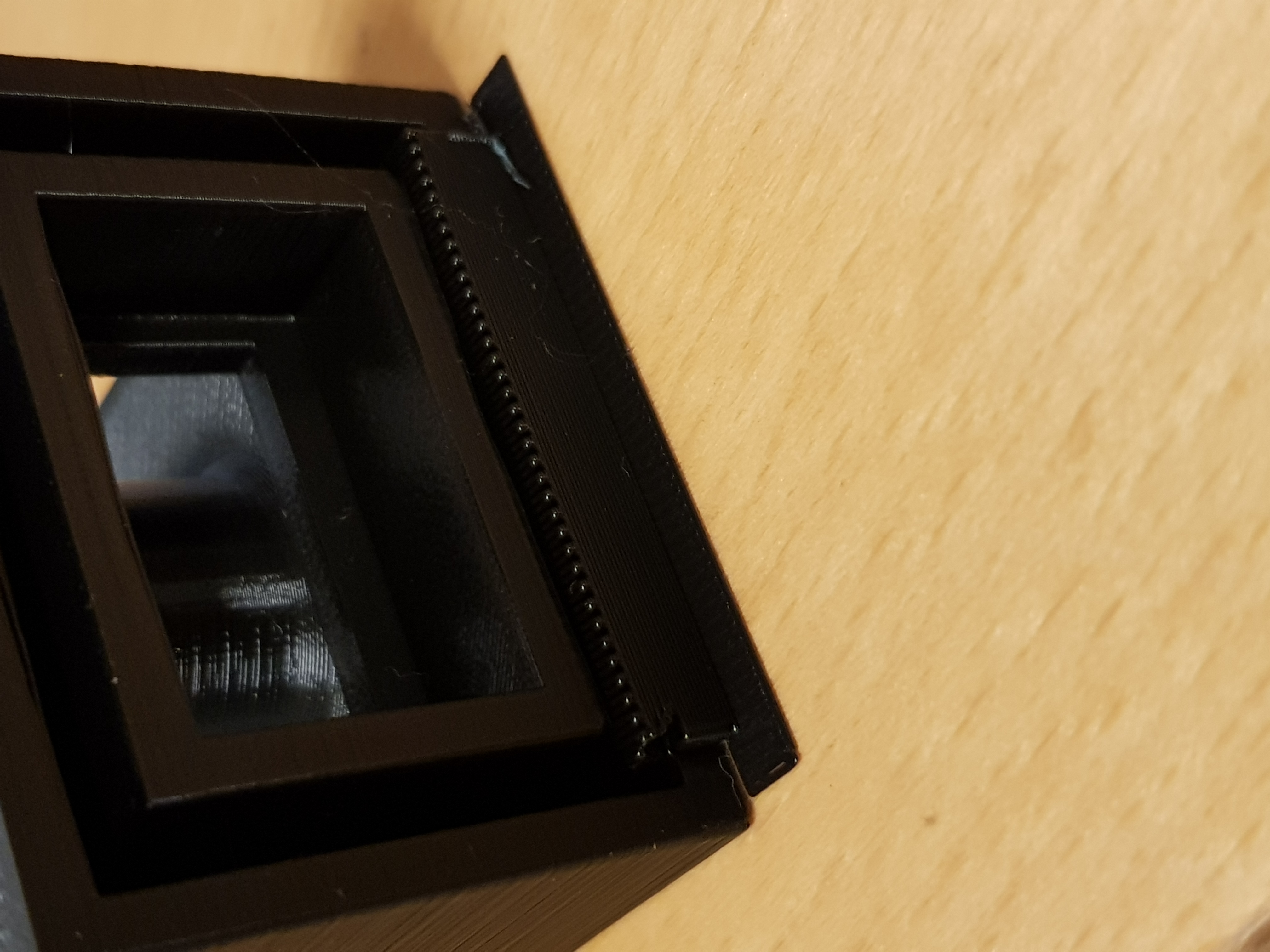
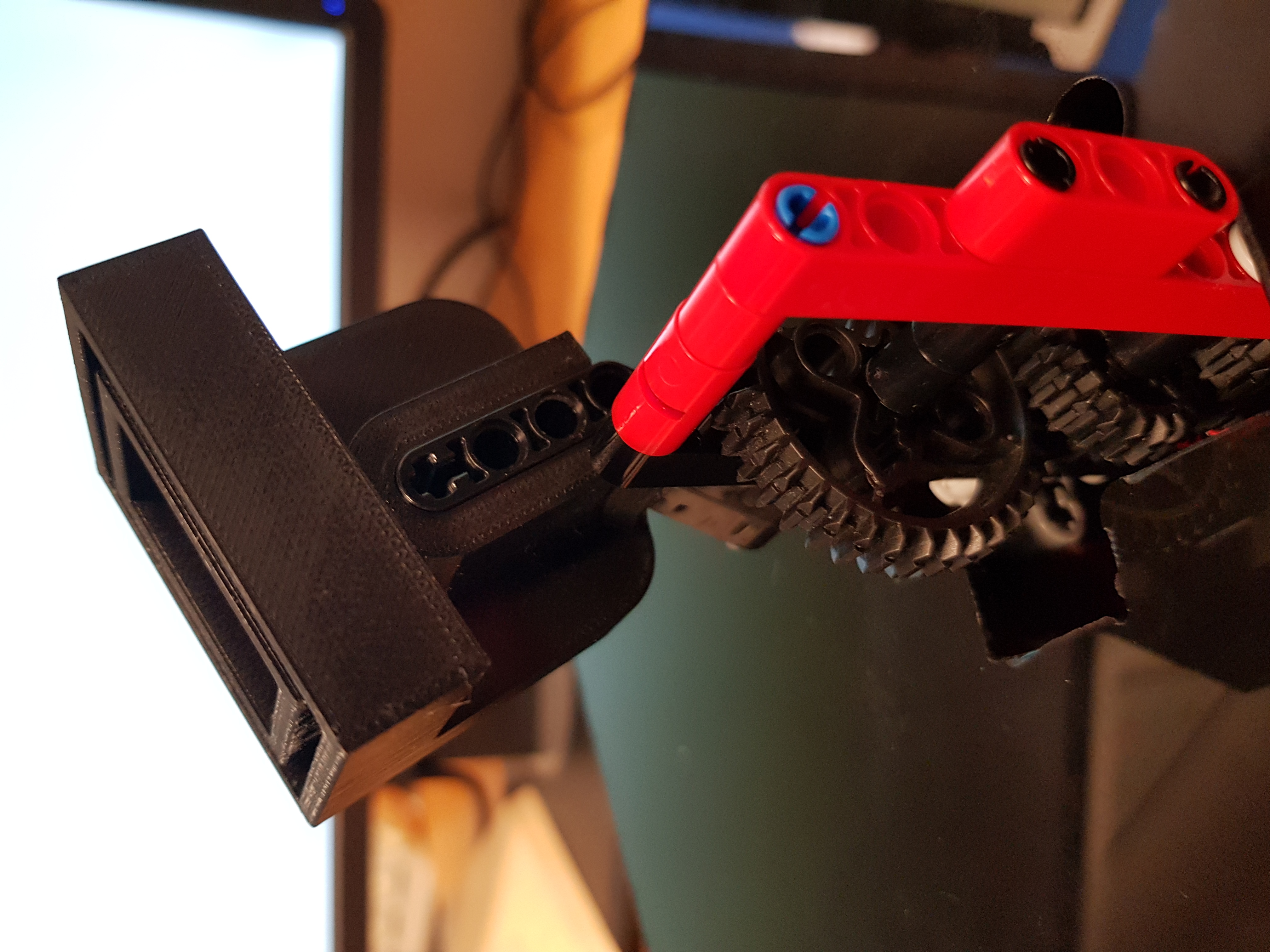
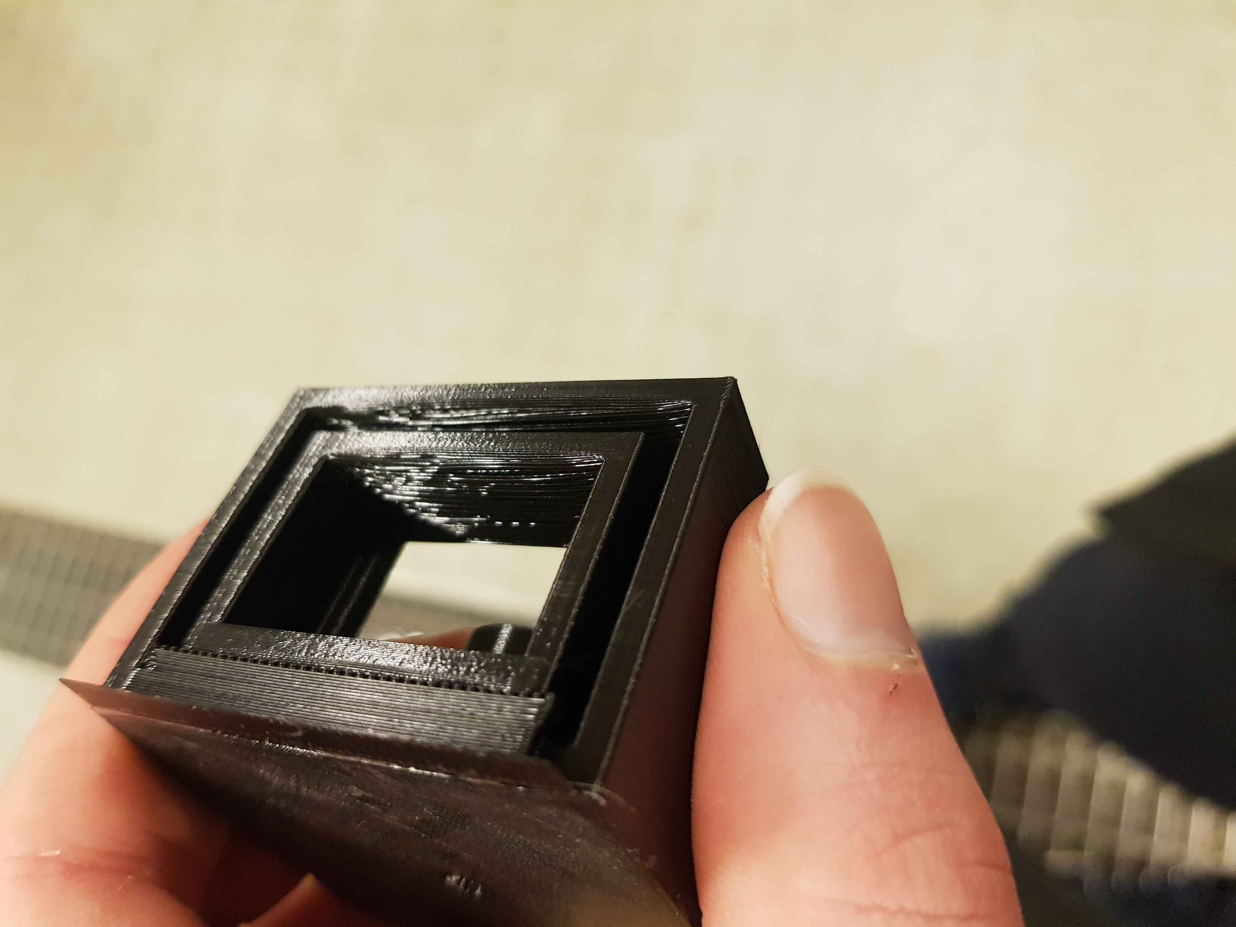
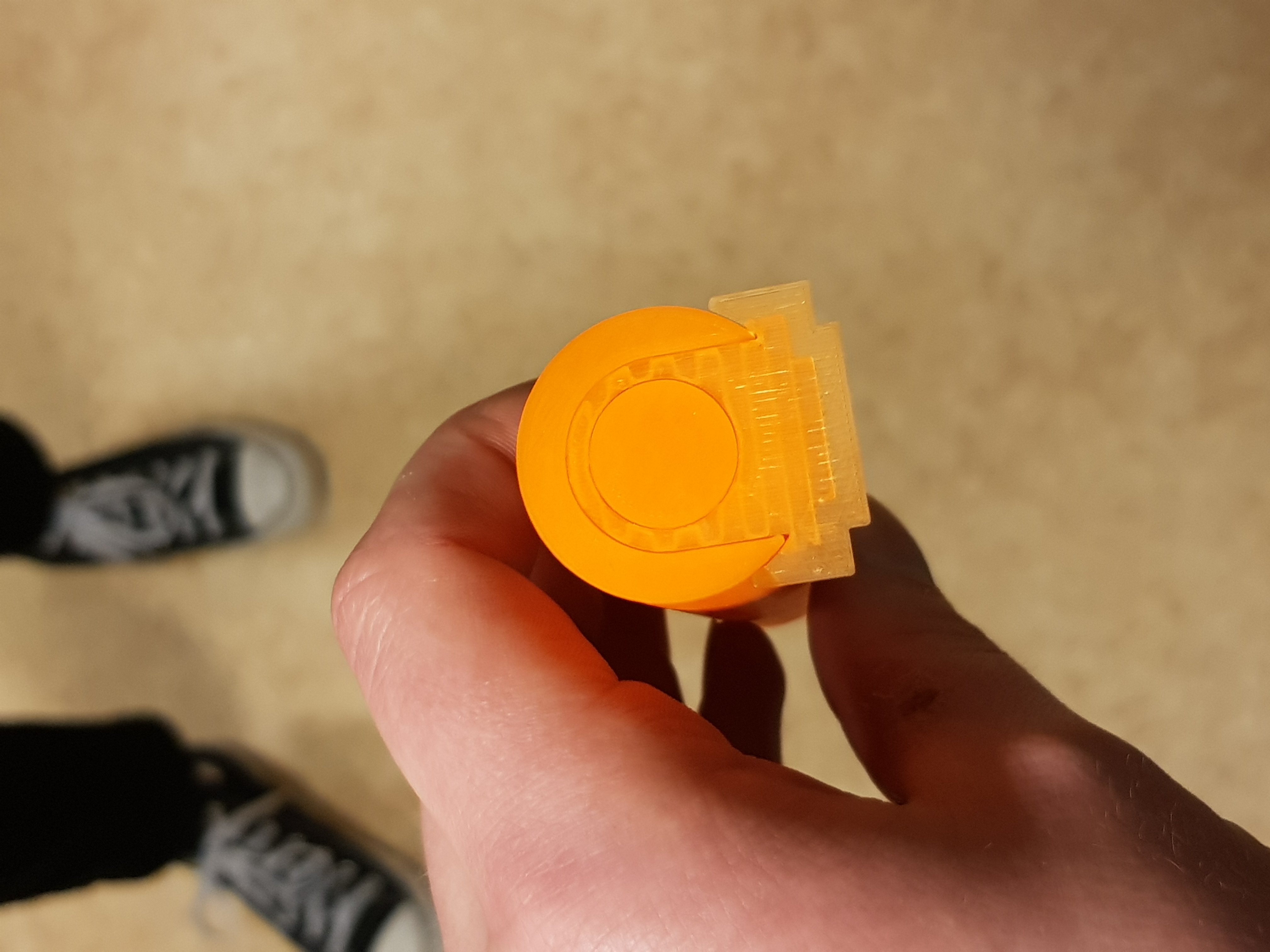
The printer printed the insert without any problems:
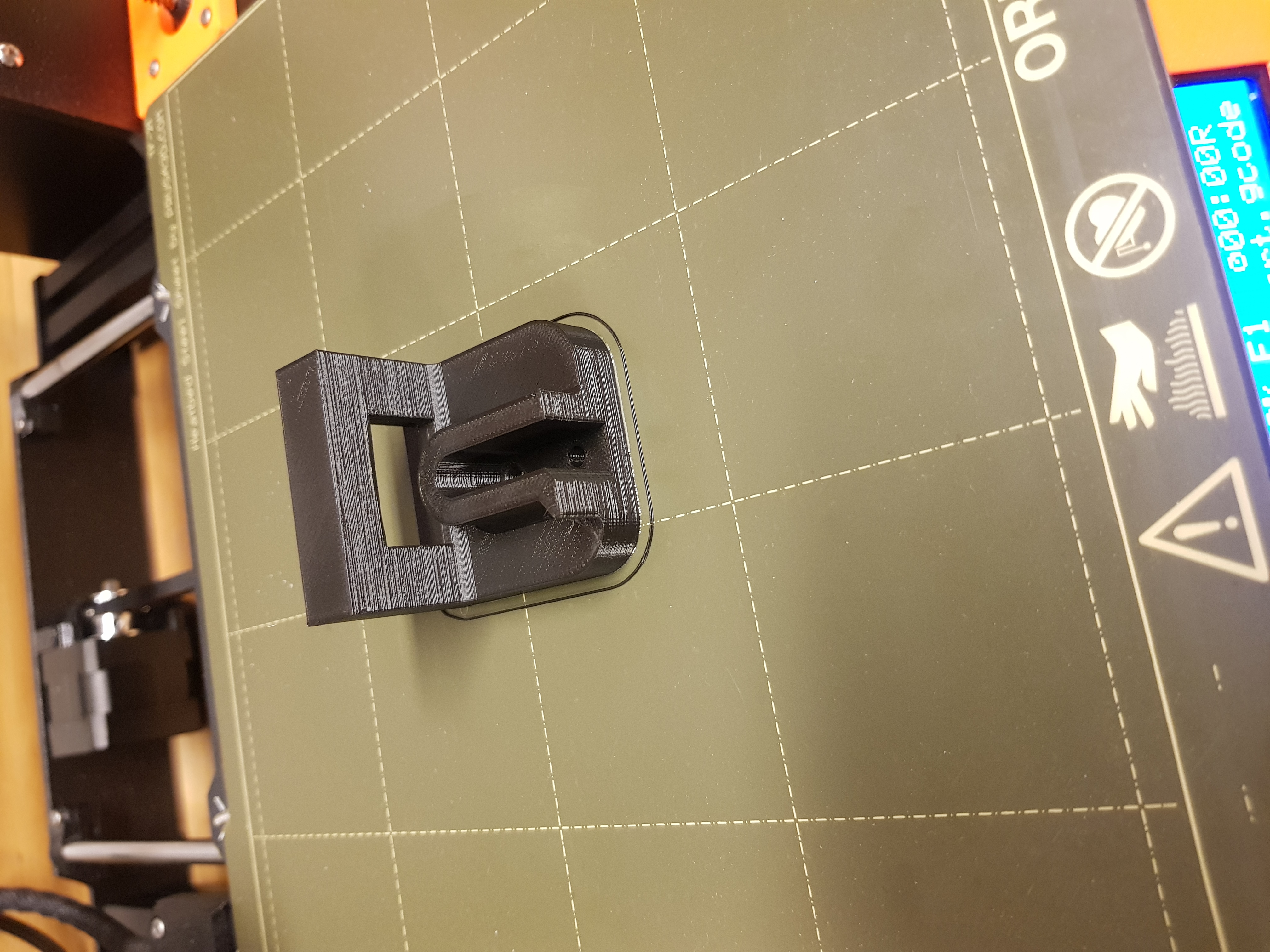
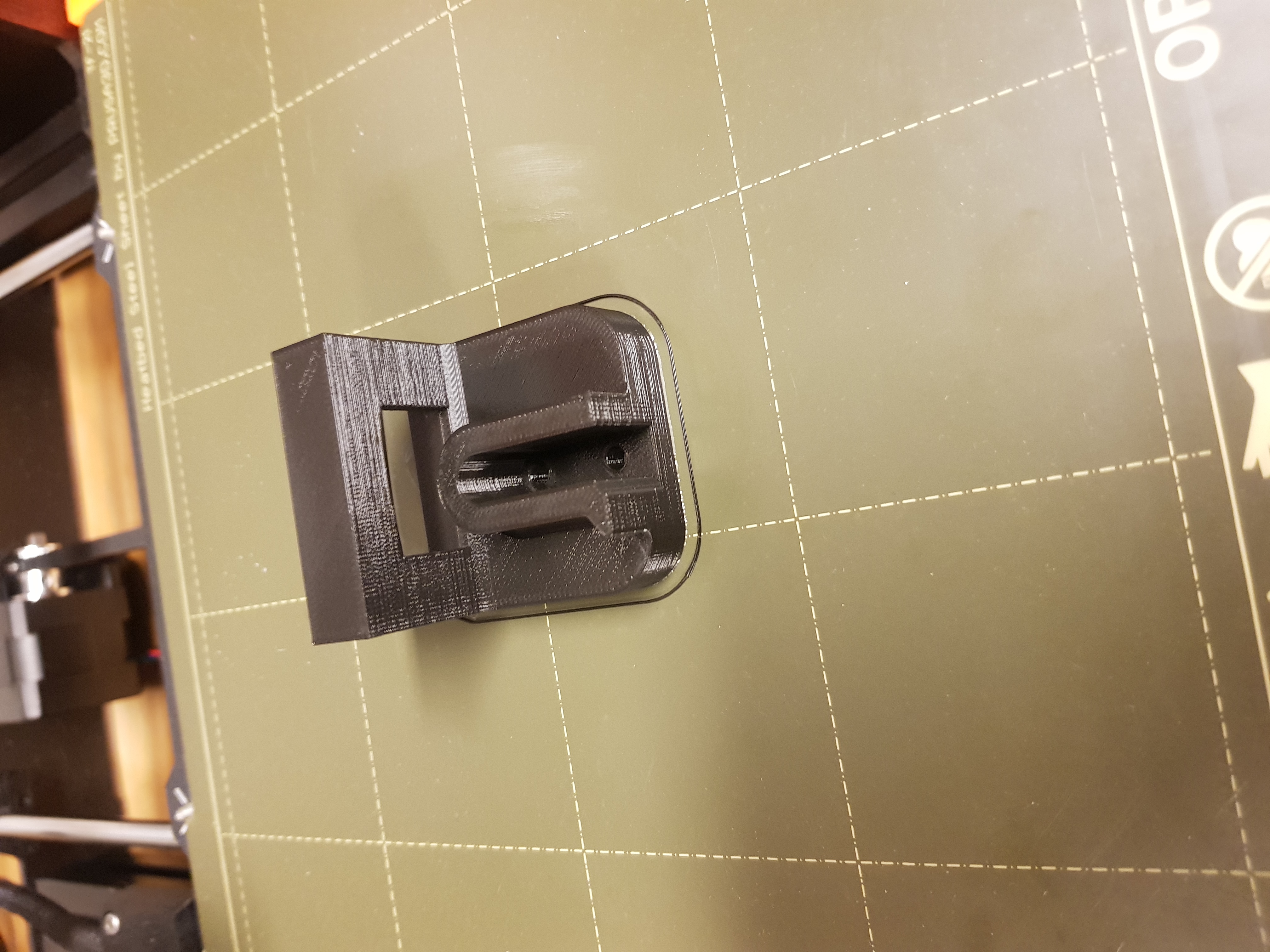
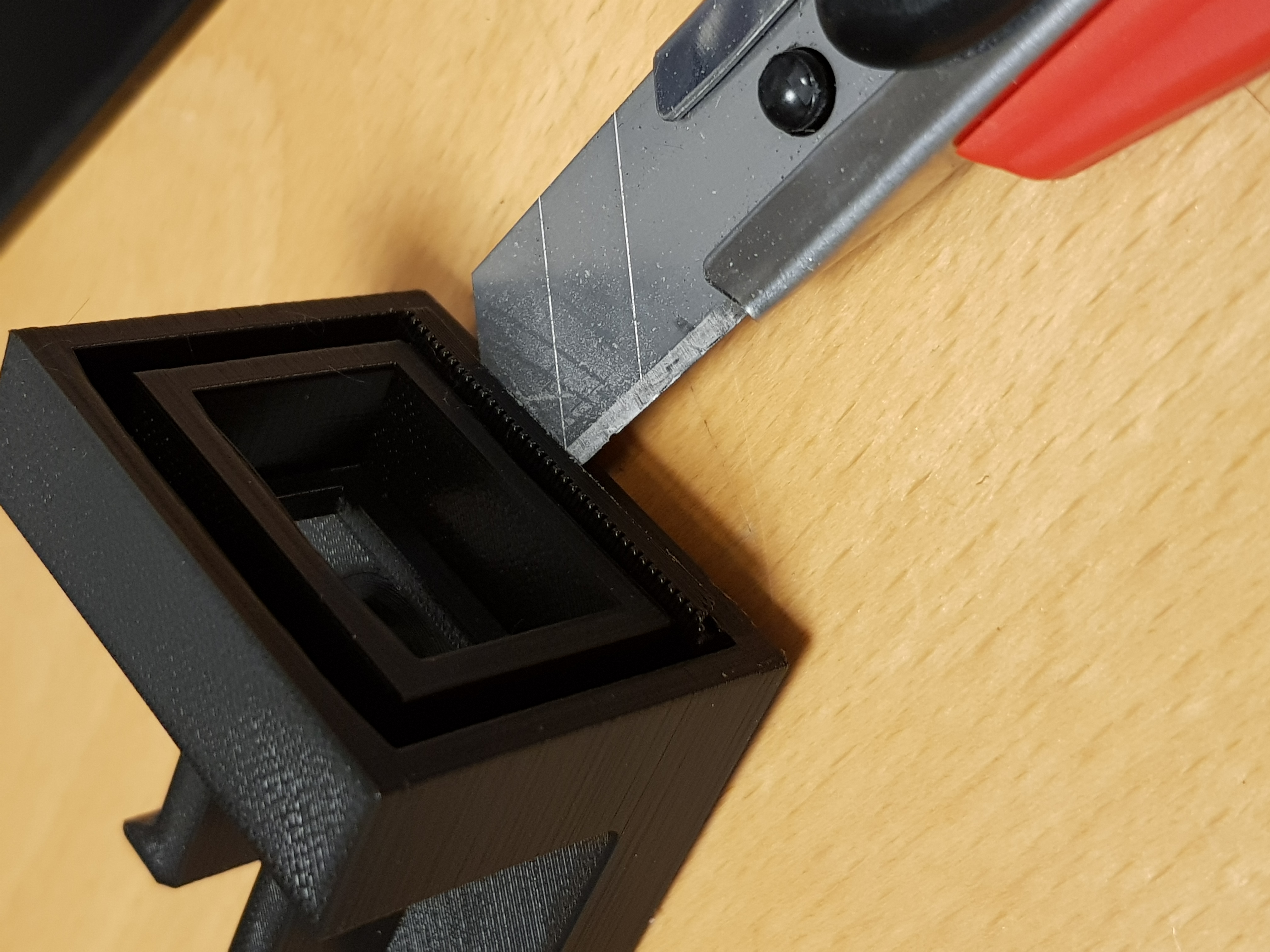
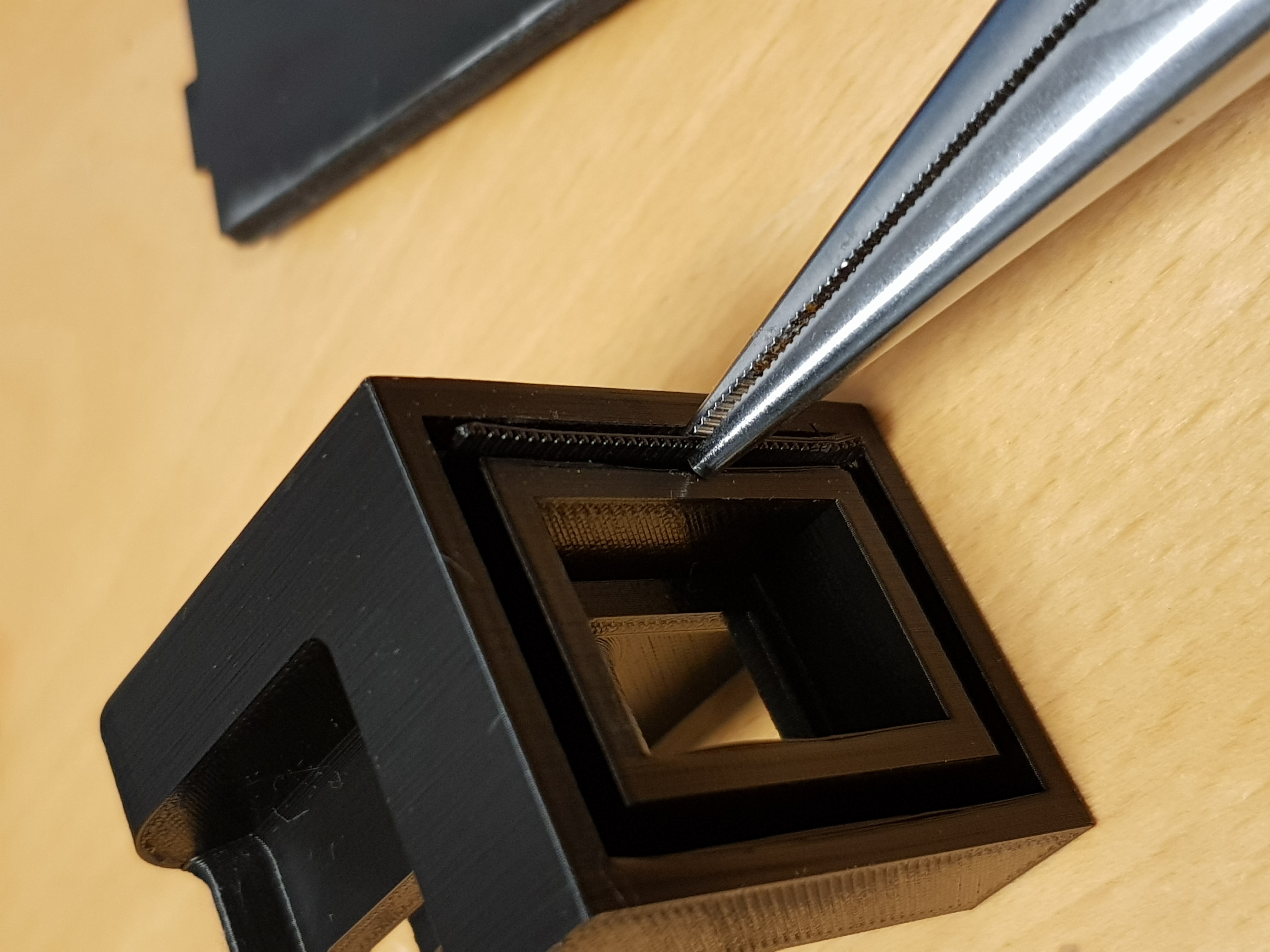
Next, I removed the support material using a tablecloth knife and pliers:
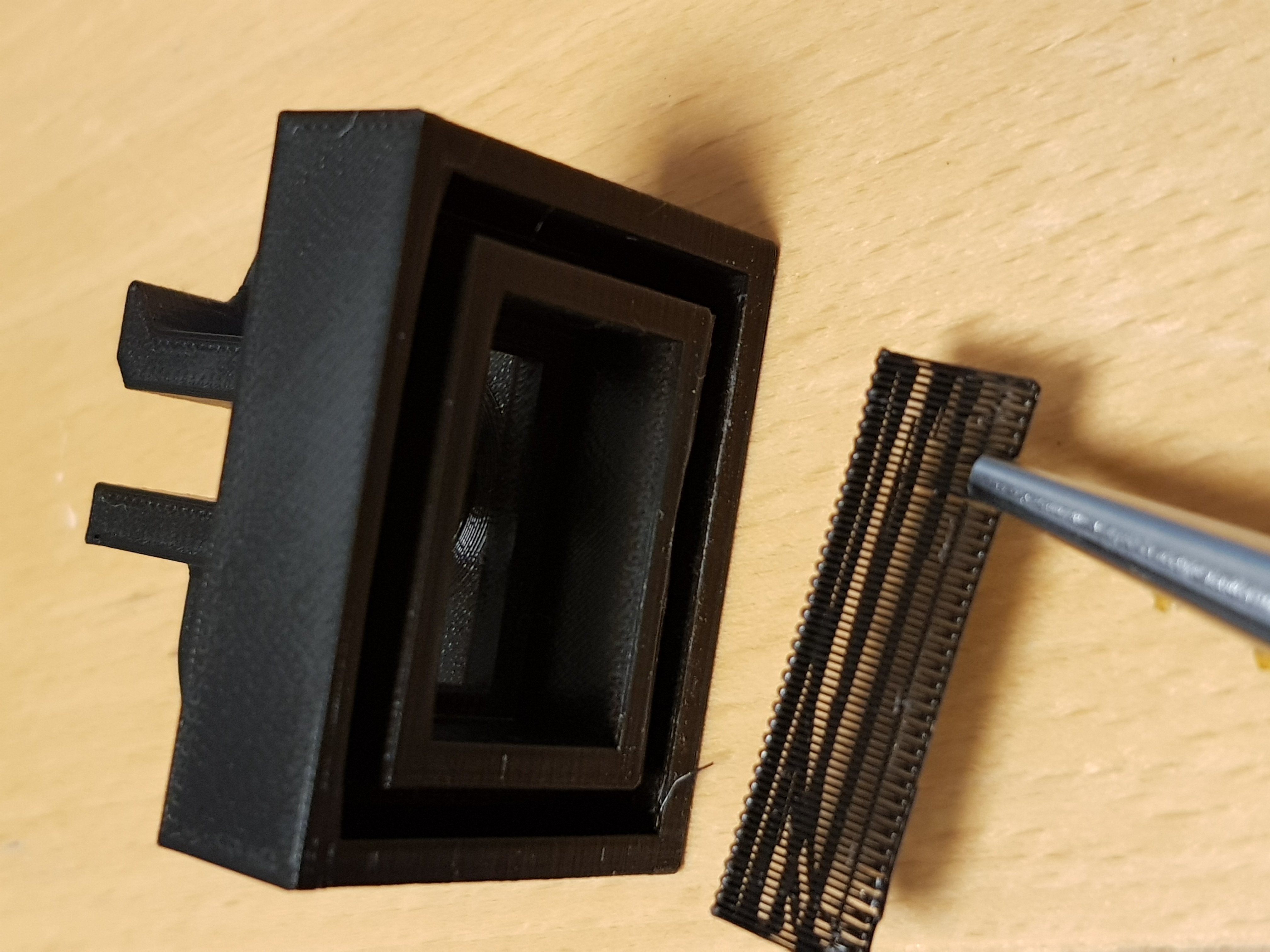
When the support material had been removed, I checked the pressfit of the insert. It fitted nicely with the intended 3 mm plexiglass. In the robot itself we actually used a black 3.15 mm material and therefore we had to file both the insert and the plexiglass. The insert did thought fit the Lego brick perfectly.
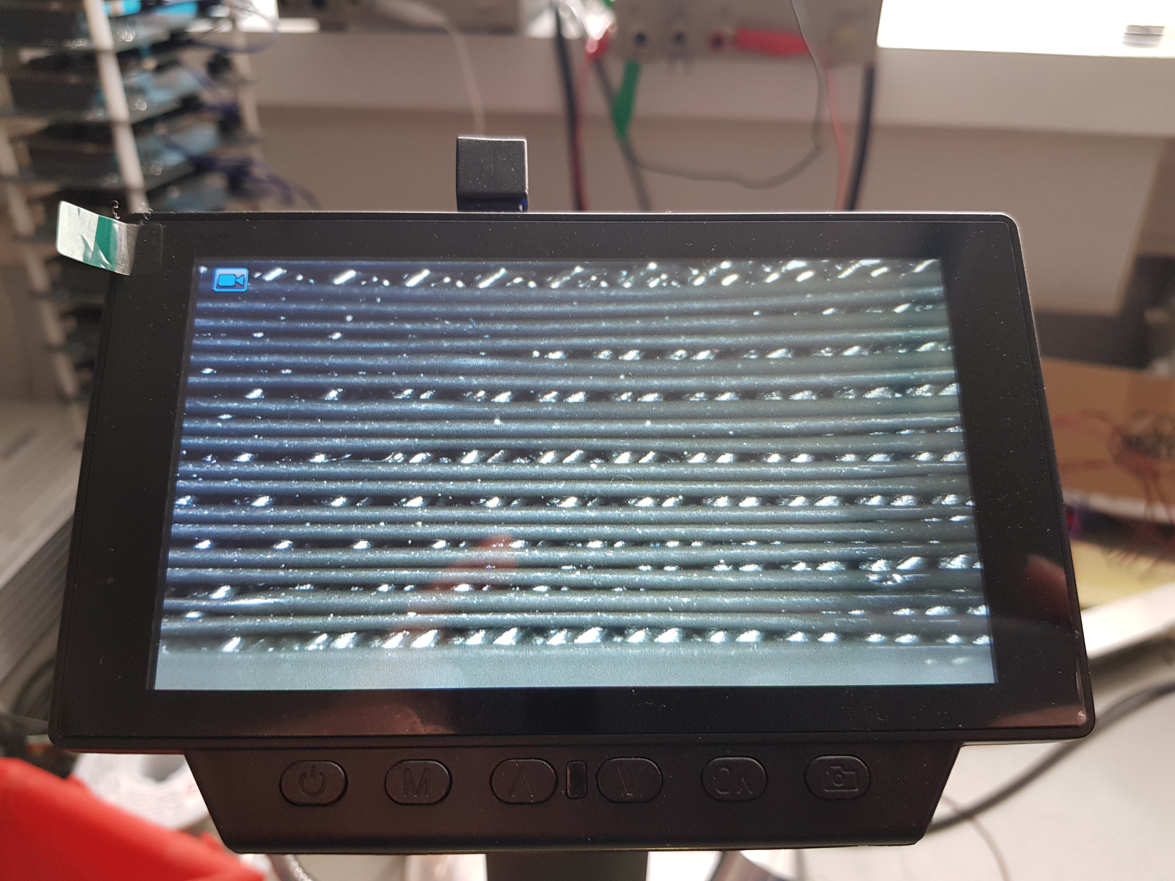
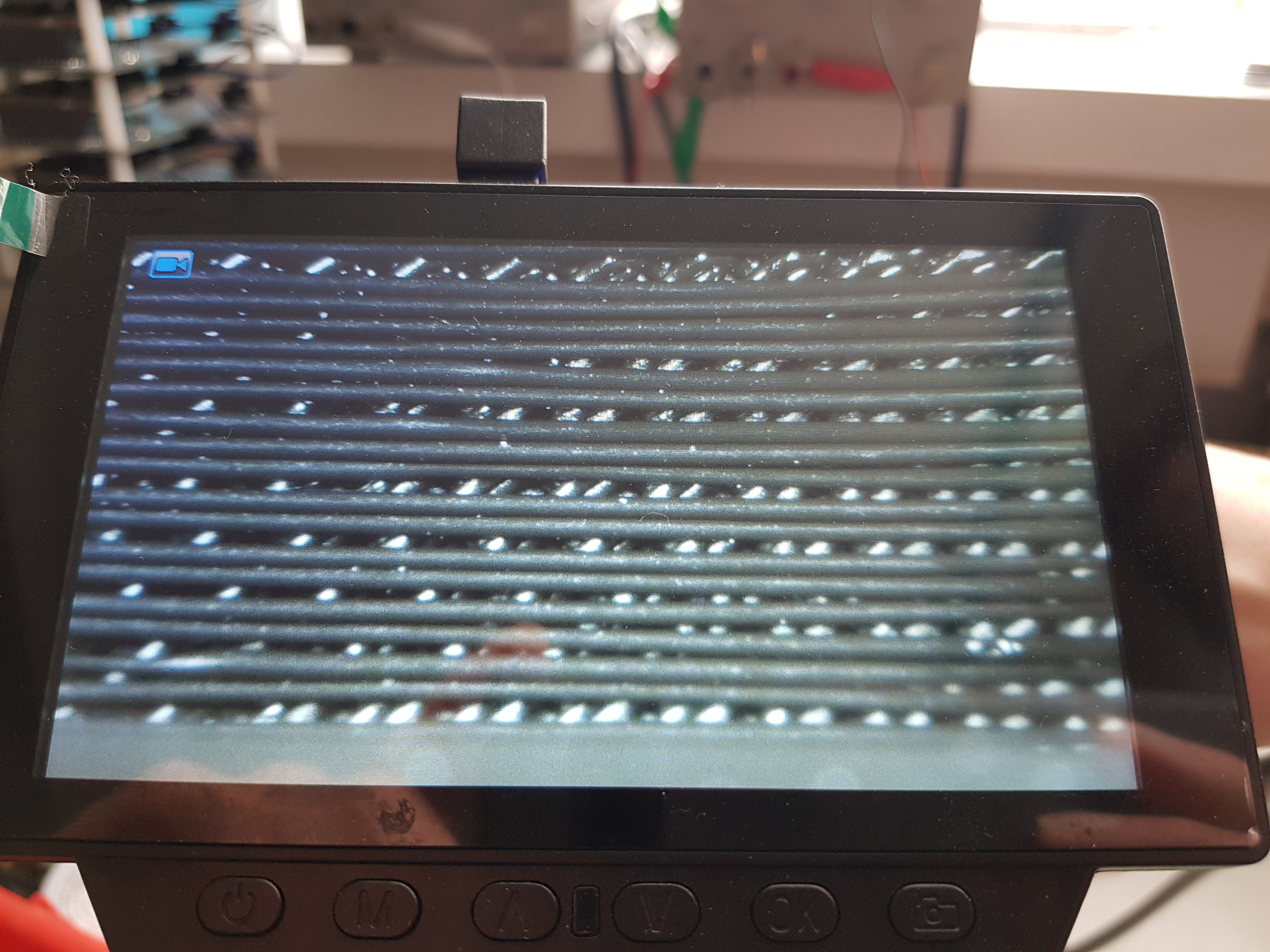
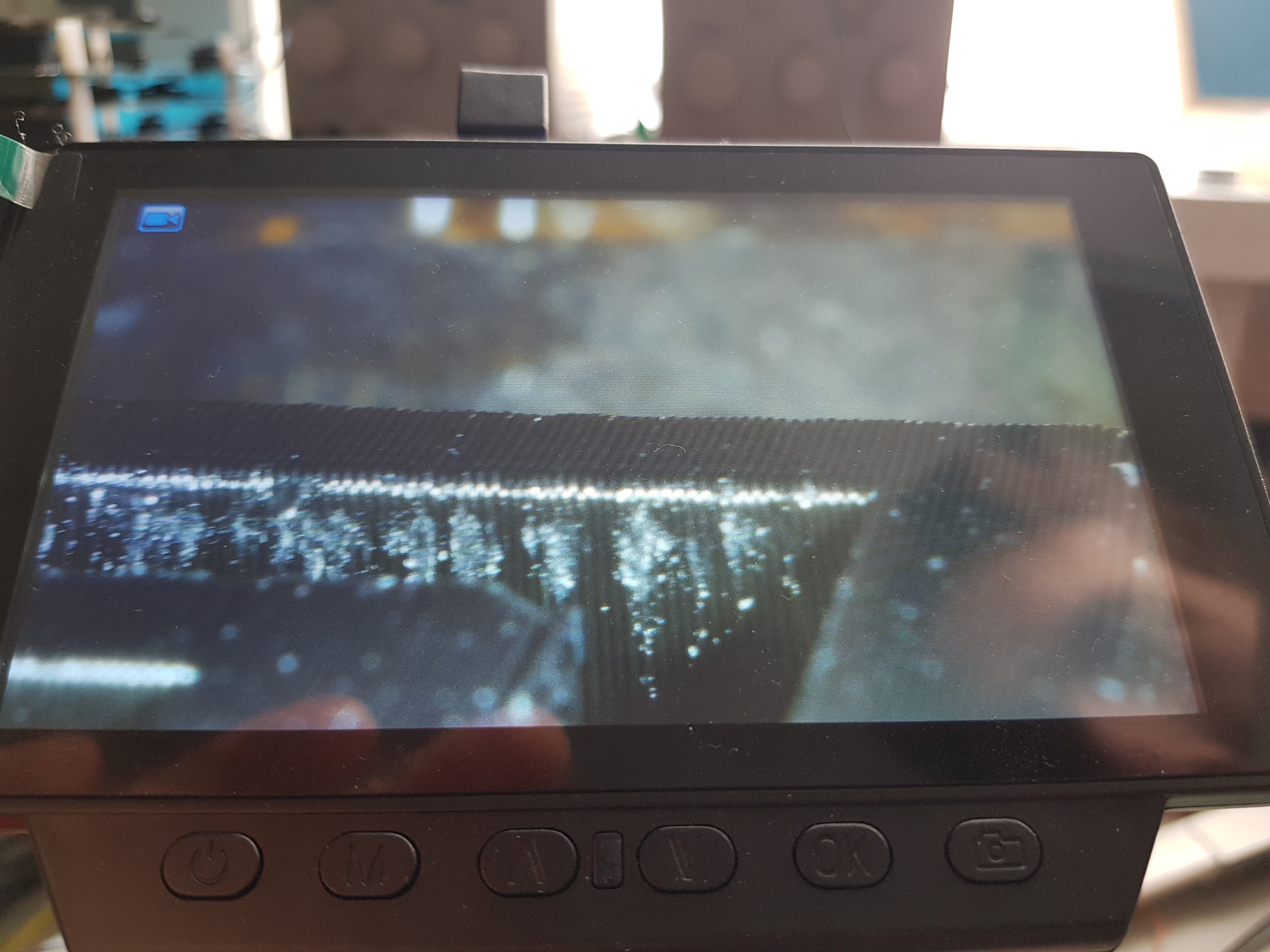
At last, I inspected the print quality. The results were: the printer should not bridge more than 30mm without support material. The inspection was done using eyes, cameras and macro camera for electrical use.
Worktime: 5.5 hours.
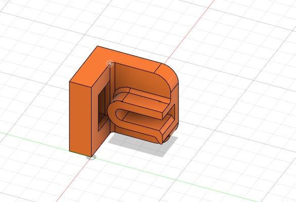
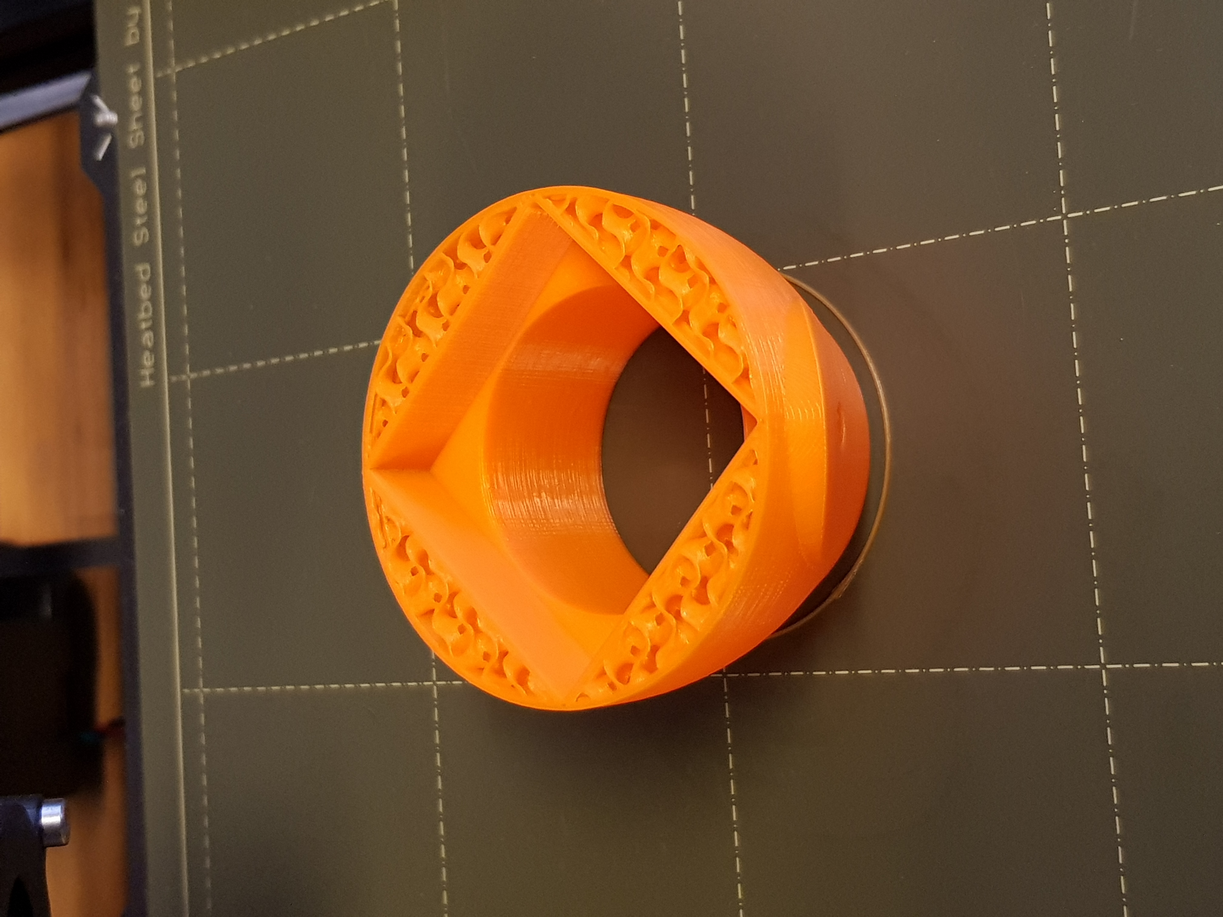
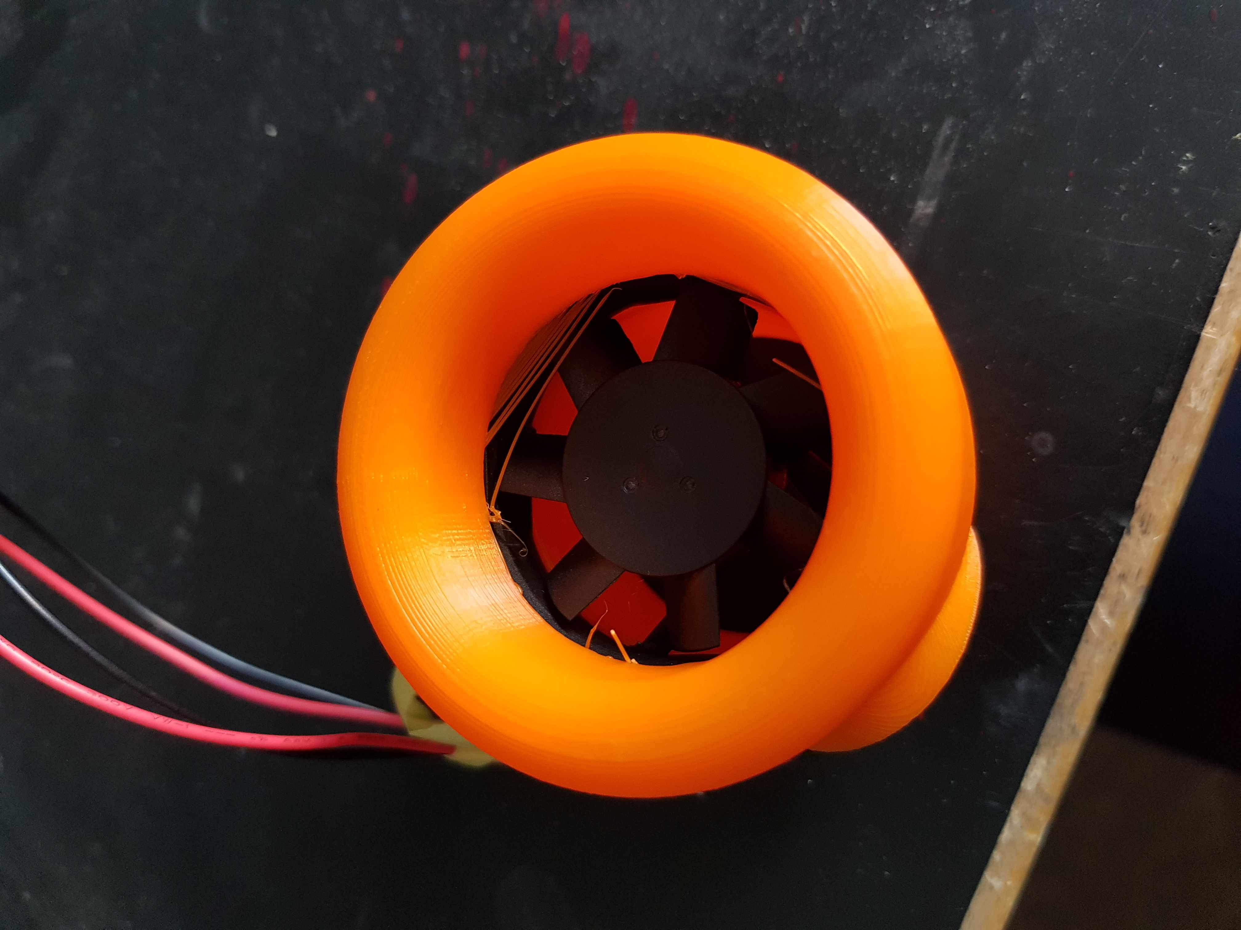
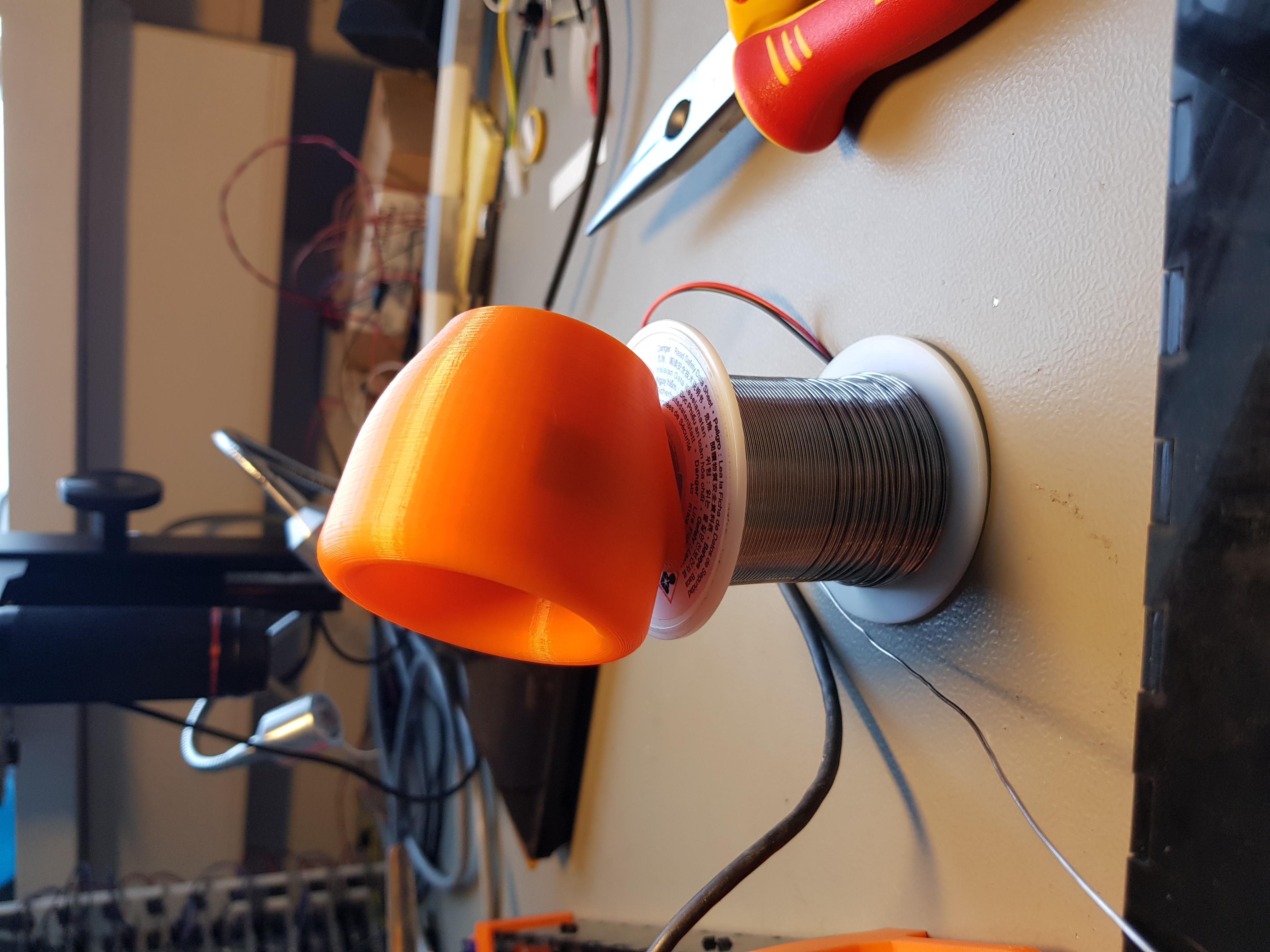
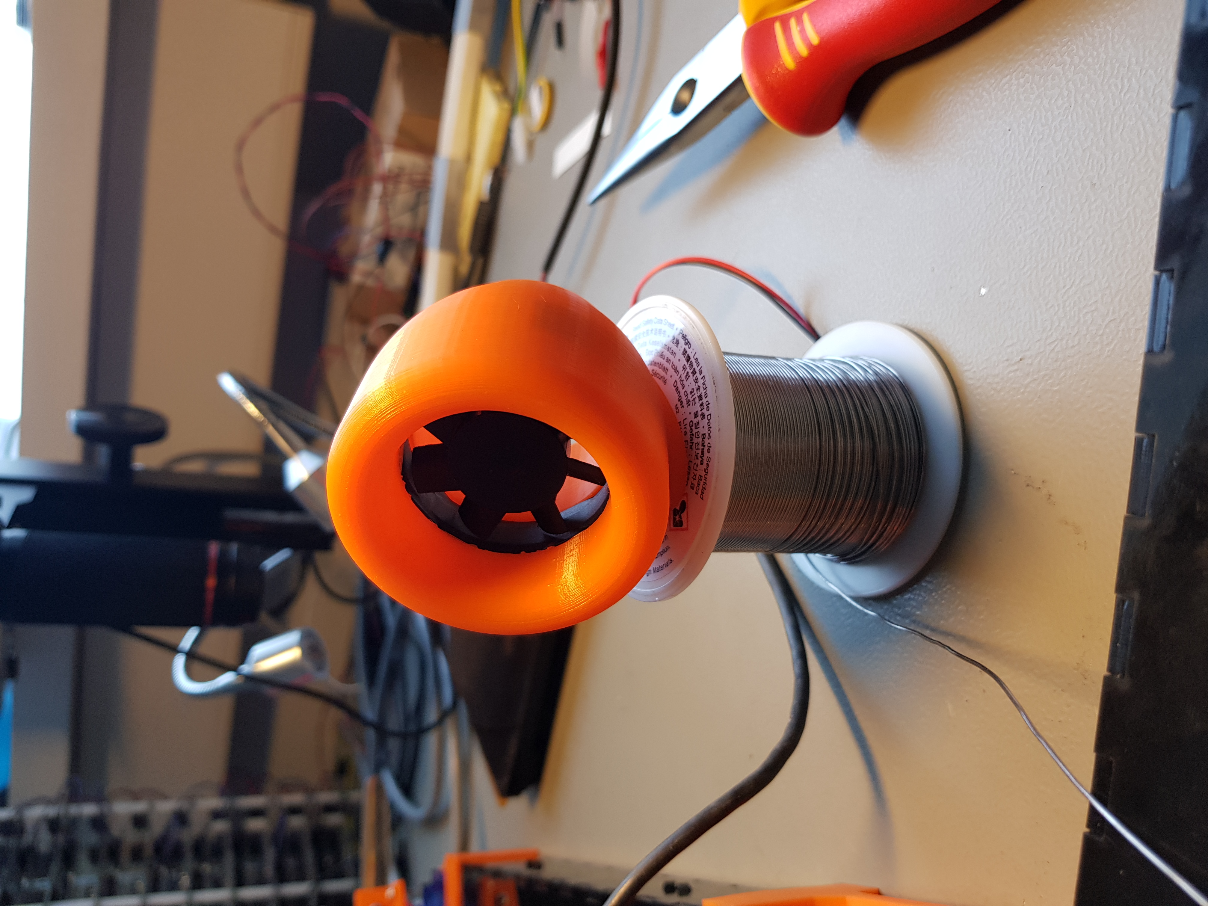
Designing a fan duct
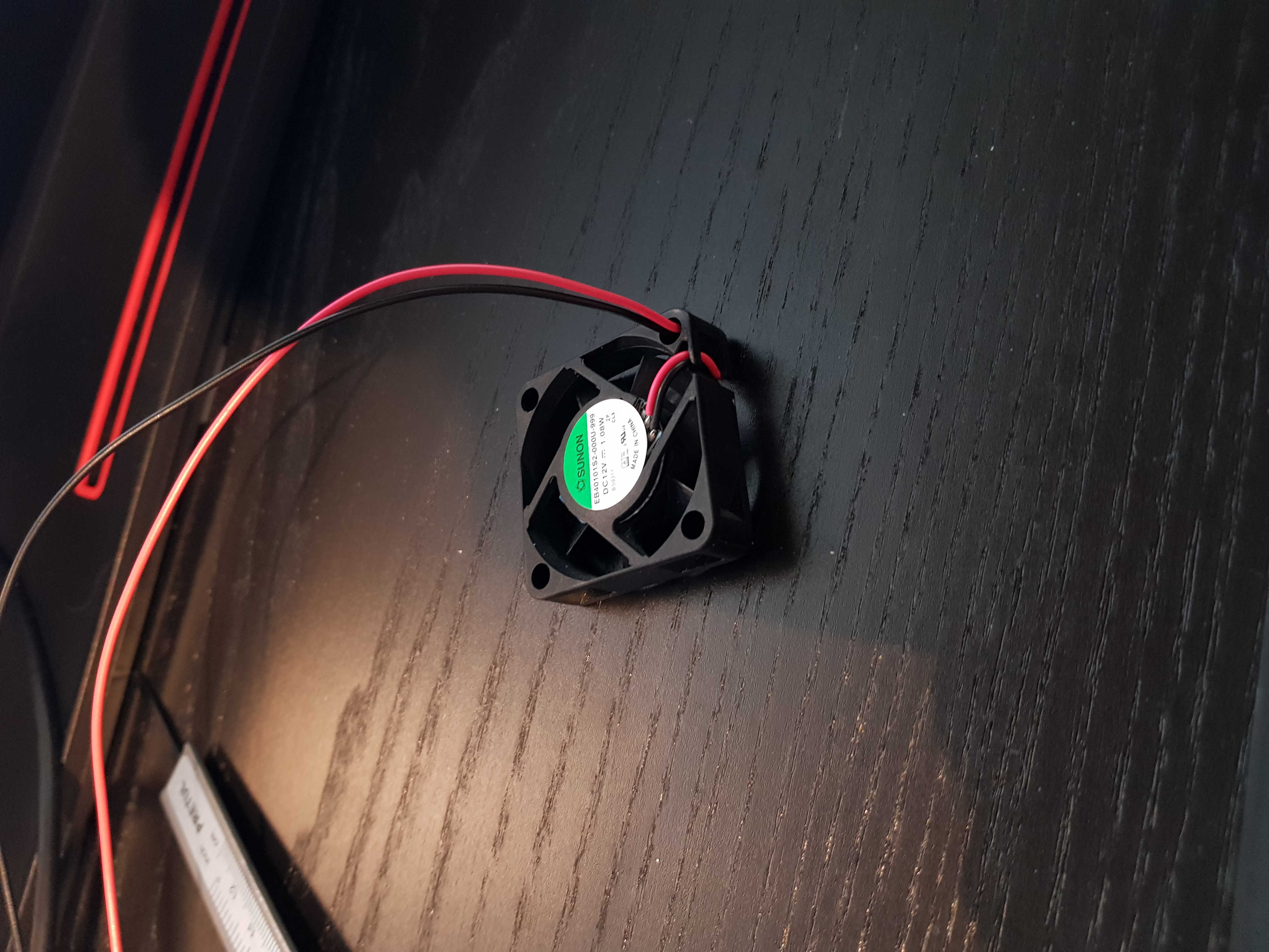
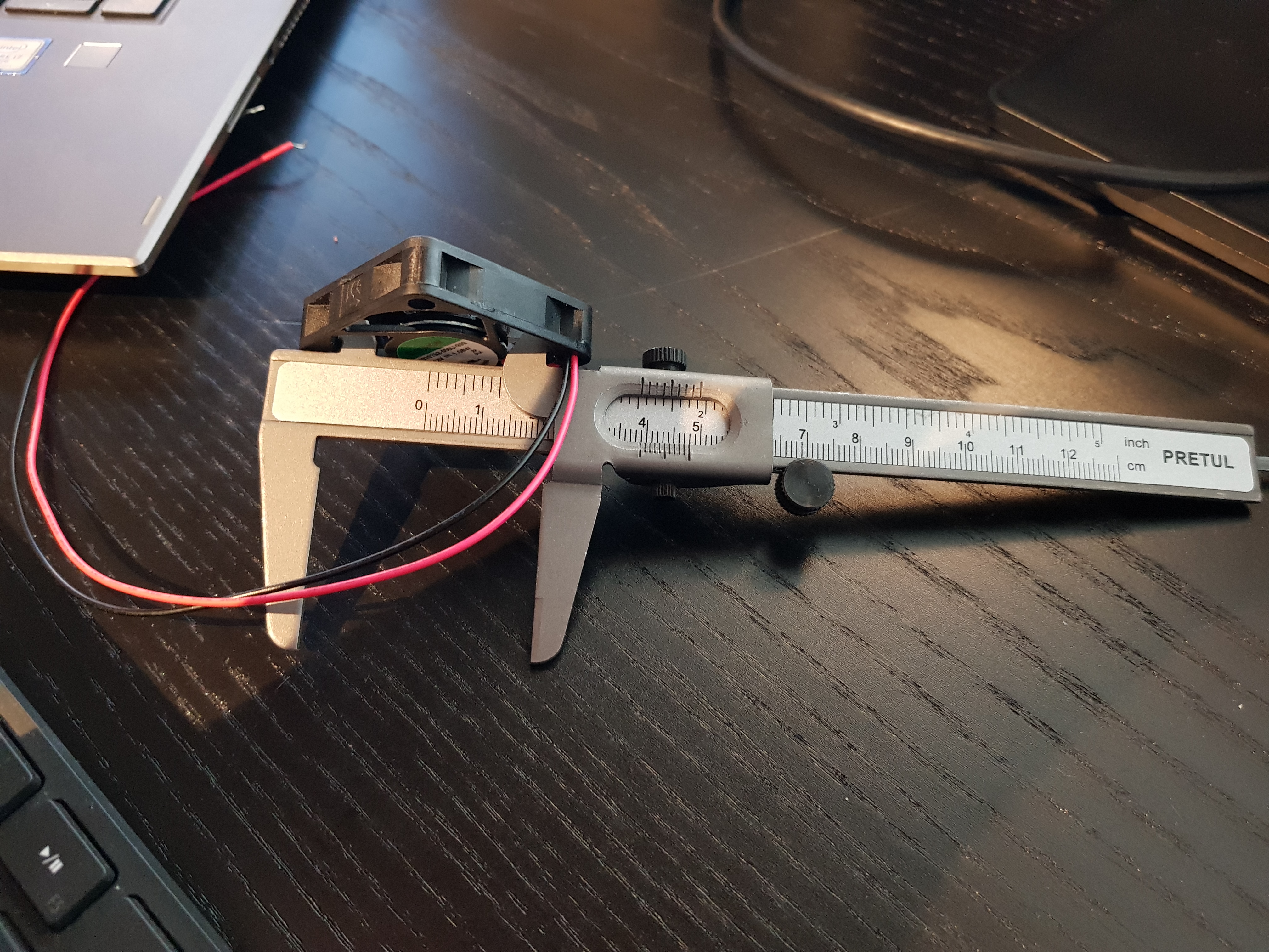
I wanted to print something, that could not be made with any other method, and still be useful for the soup robot. Then I got the idea of printing a duct around a small fan, used to cool the soup. The duct would be a one piece, printed around the fan, making it impossible to manufacture using any other method. I started by searching on the web using the keywords: "small fan duct" but I did not find anything interesting. Me and my creativity were on our own for this part. I started by measuring the fan and added the measurements to the parameter table in Fusion.
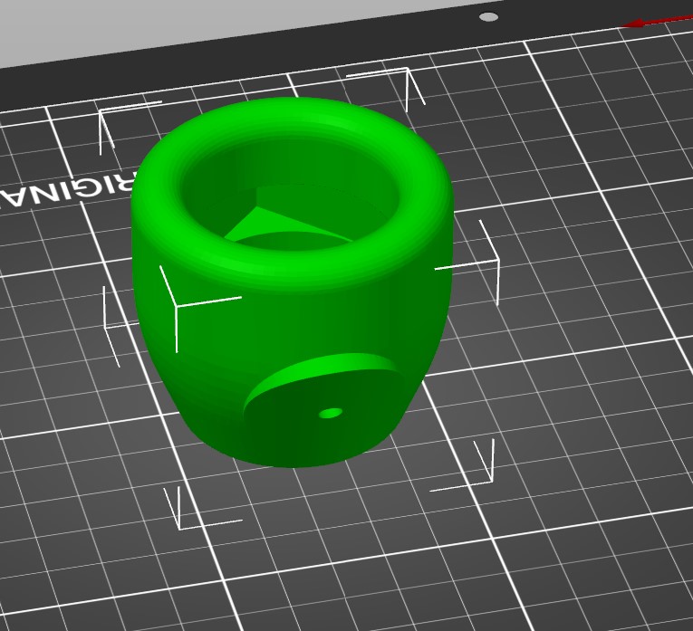
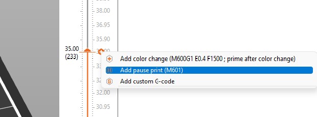
At that point, I had gotten pretty confident in drawing fancy shapes, so I drew the duct with a pole (stand) using all sorts of fancy features, such as loft, sweep, offestting planes at an angle and many more. The drawing only took about half an hour. When I tried slicing it though, I realized that I had to split the part in two because otherwise I would use way too much support material. I did so and sliced the duct with a stop to be able to insert the fan.
Worktime: 4.3 hours.
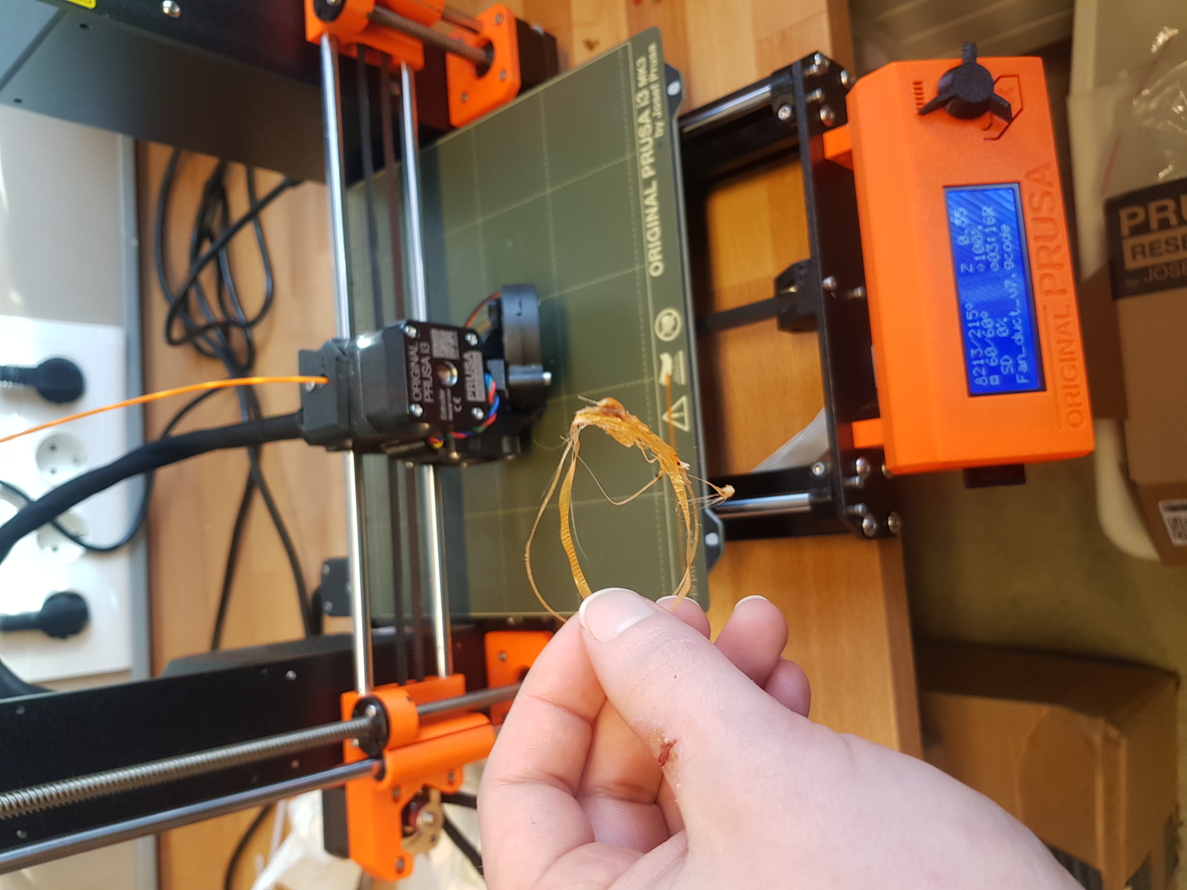
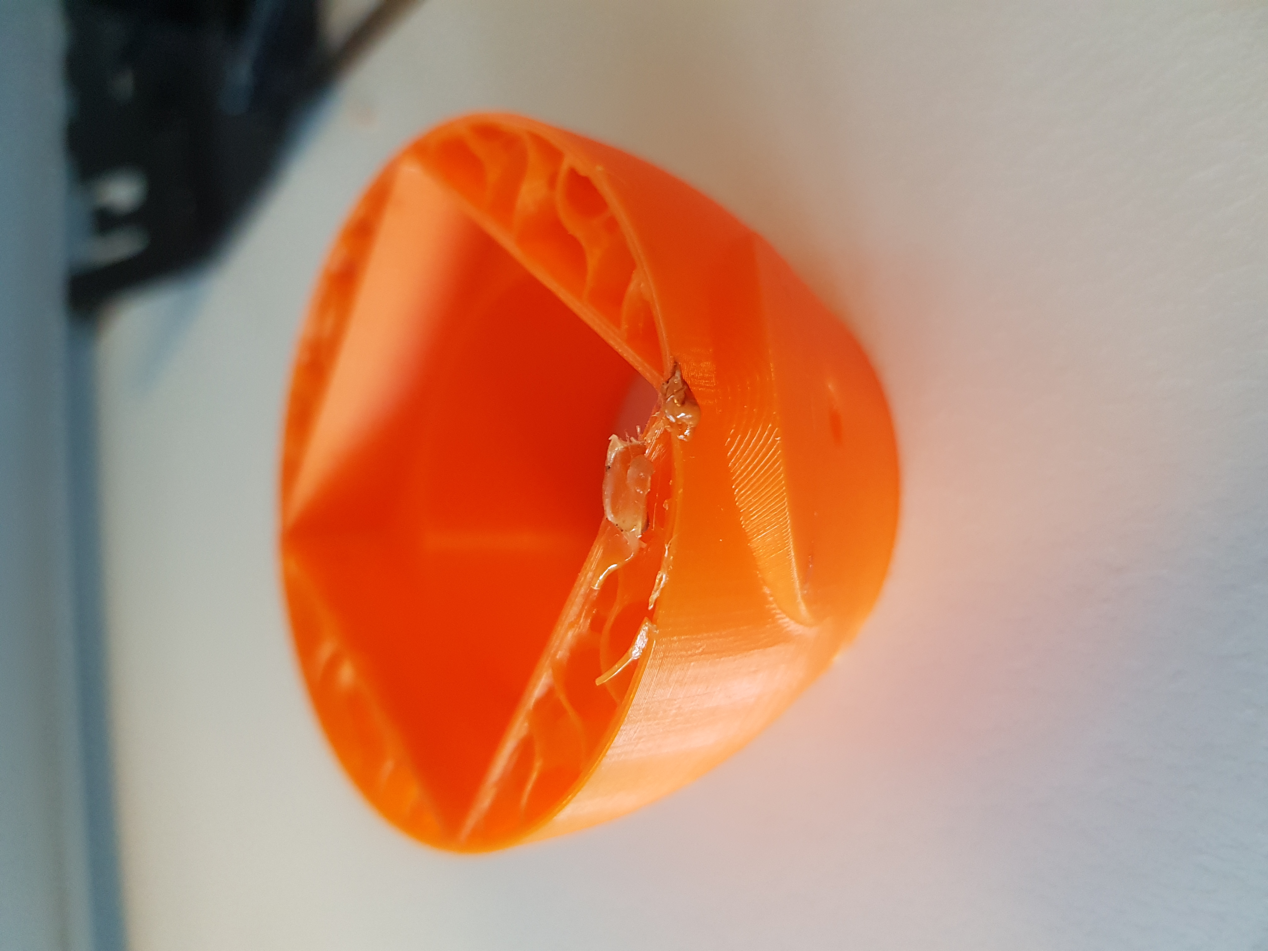
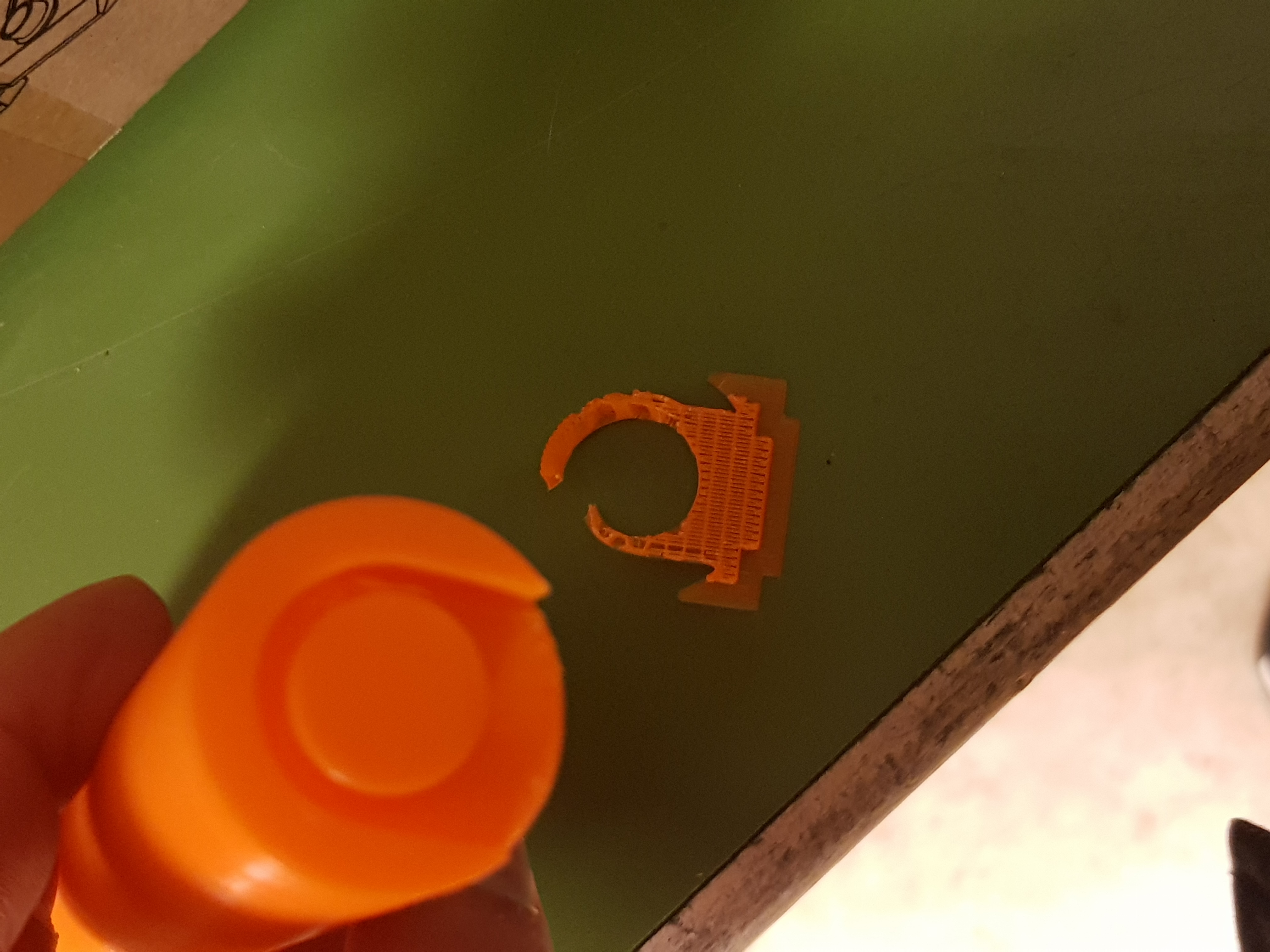
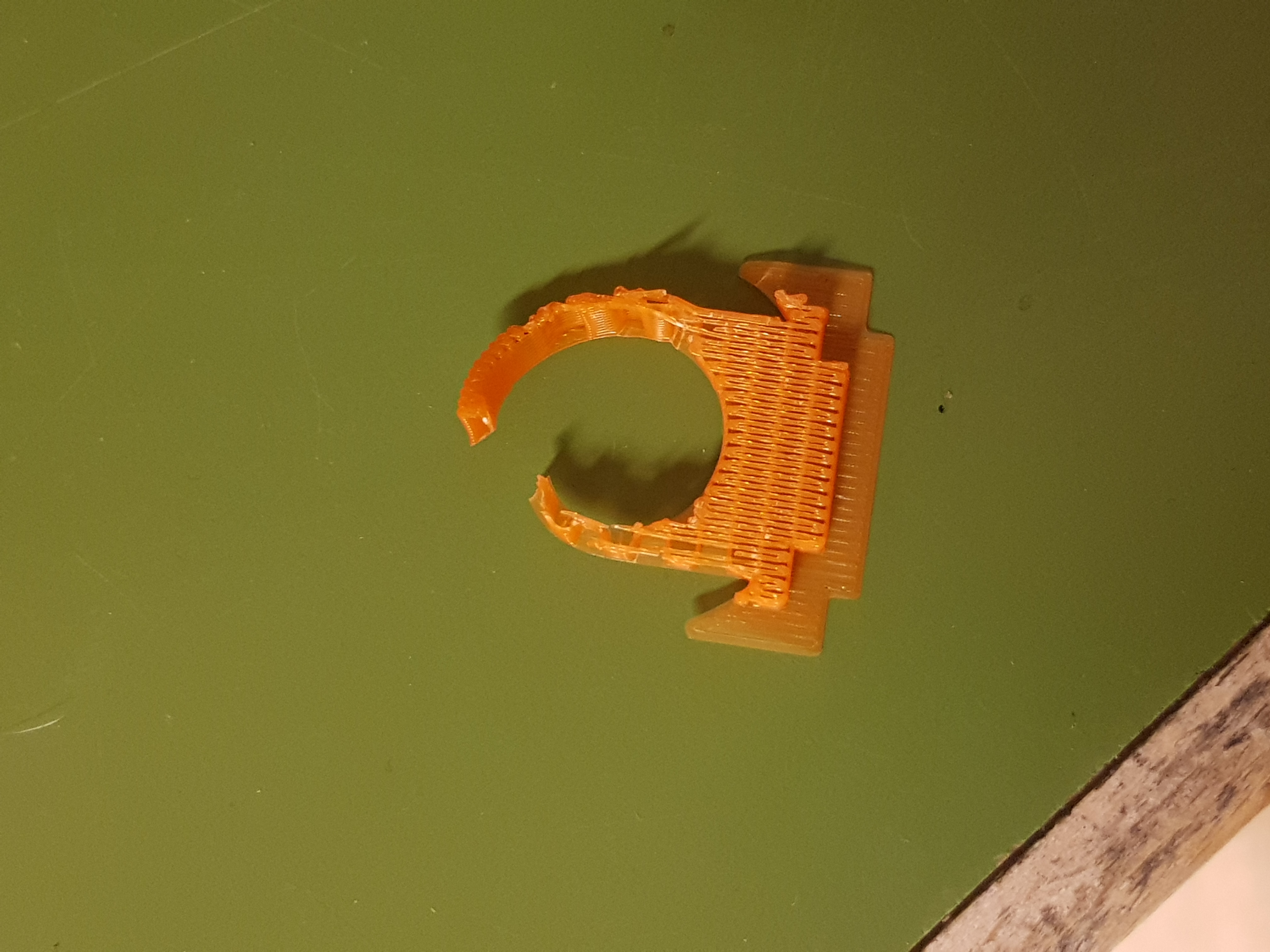
Failed prints
Next part was Unfortunately only failed prints. The printer was leaking above the nozzle, resulting in random blobs of plastic ruining the prints.
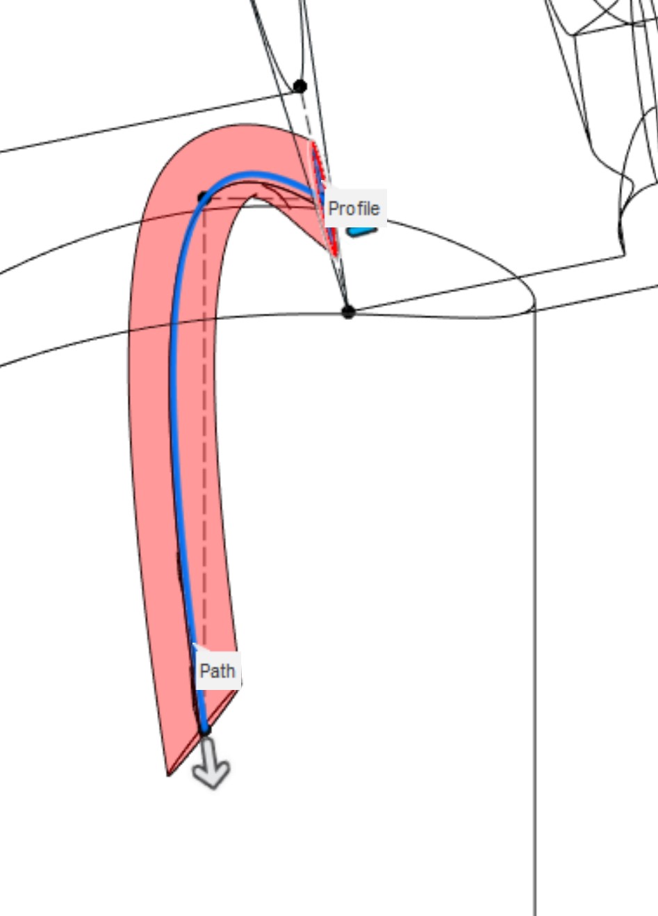
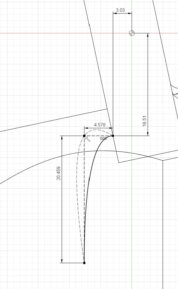
All these failed prints made me though realize a major flaw in my design, the routing for the wires took a way too tight turn inside the duct. In the figures below, the old and the new wirerouting paths are shown. The fixing was done by changing the type of a spline path, without changing the waypoints.
Worktime: 4 hours.
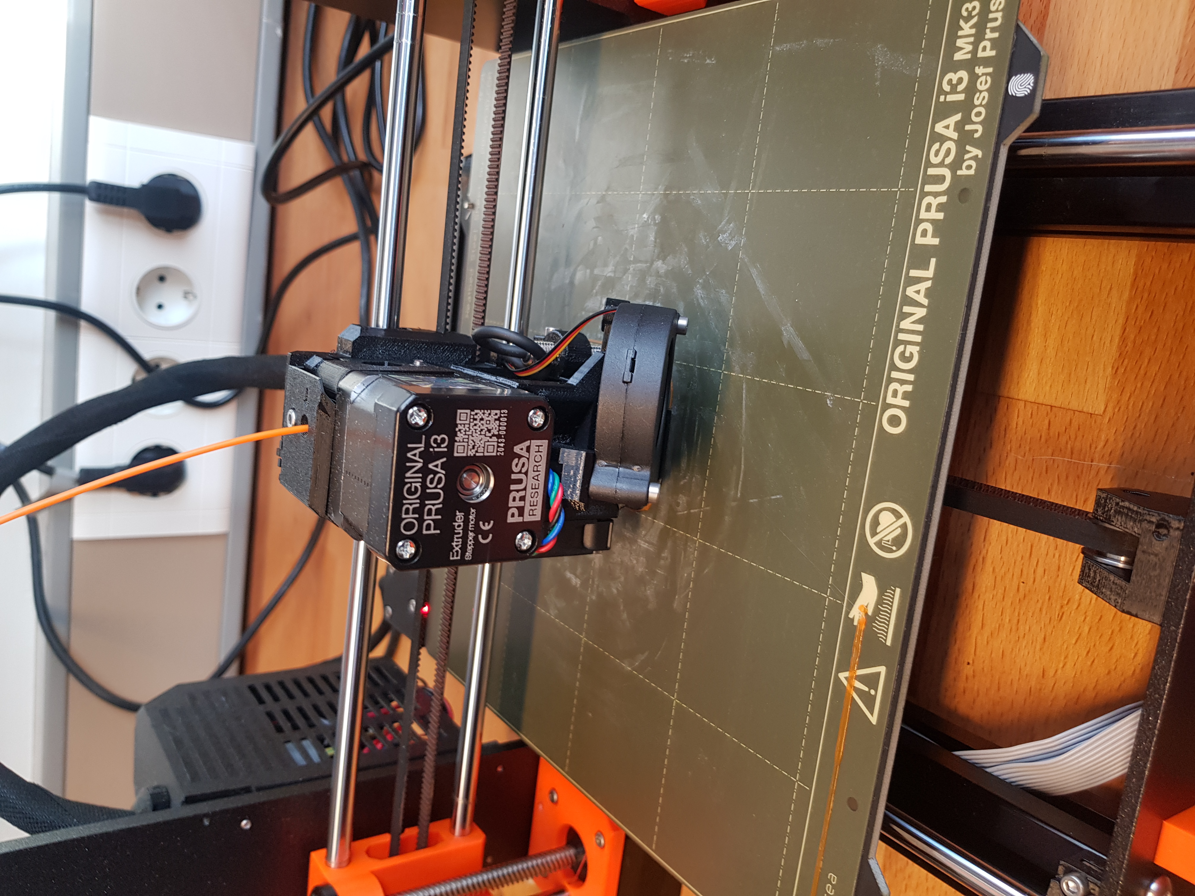
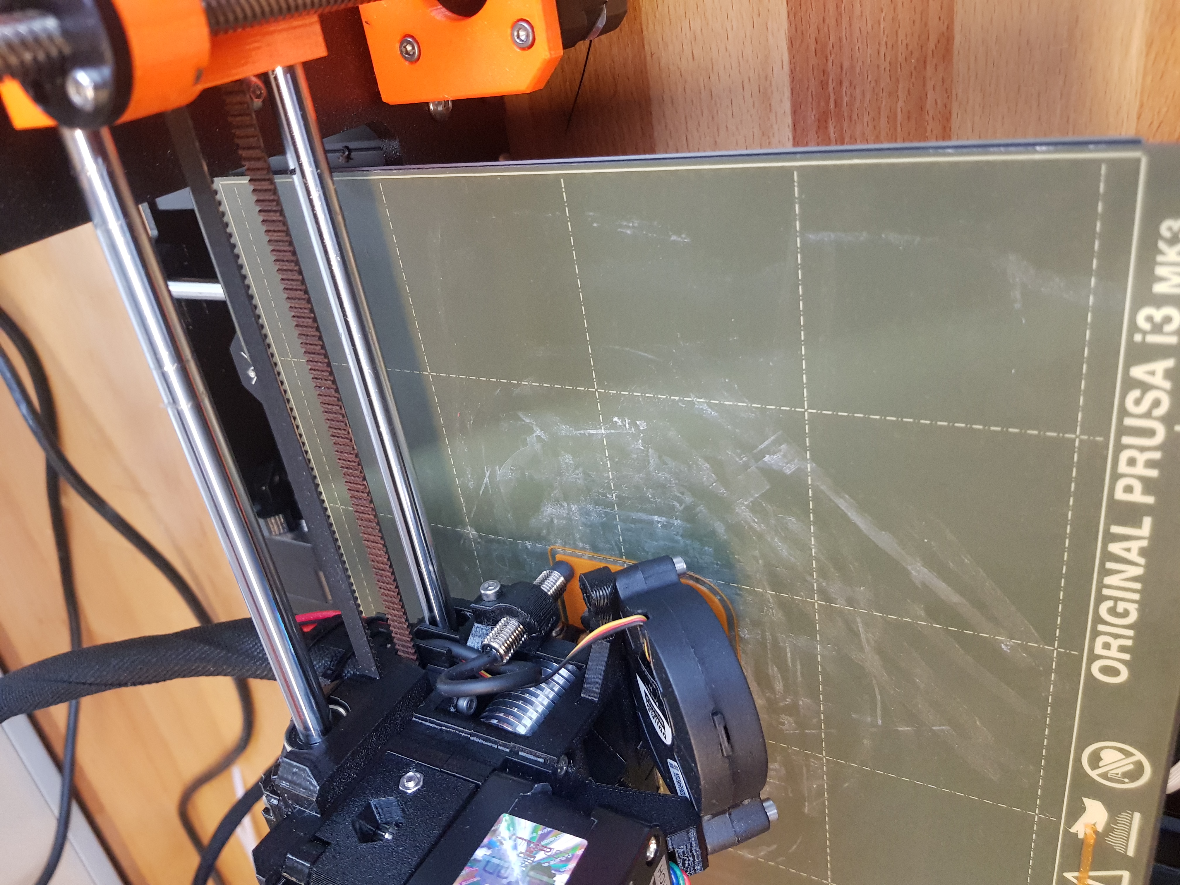
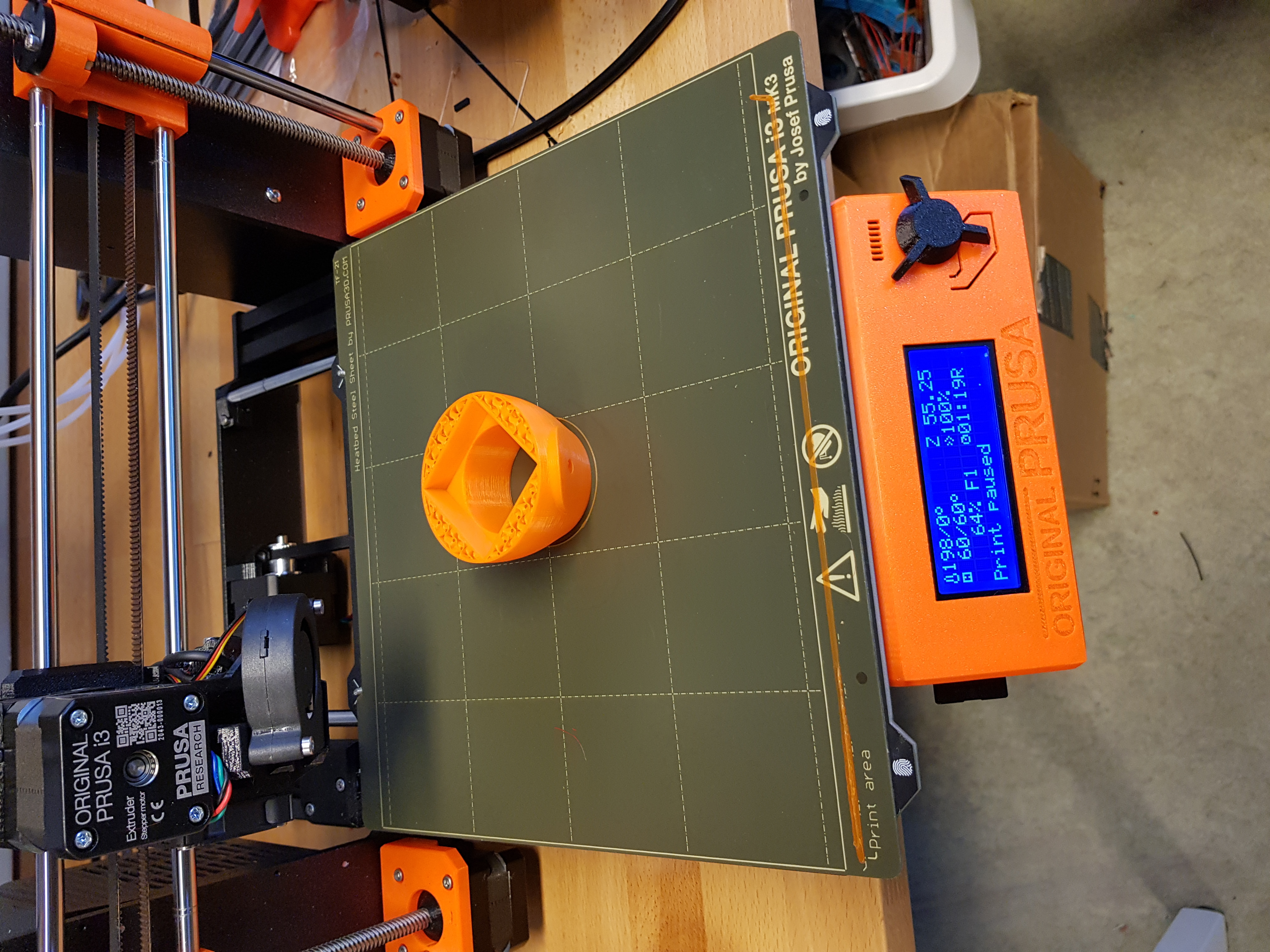
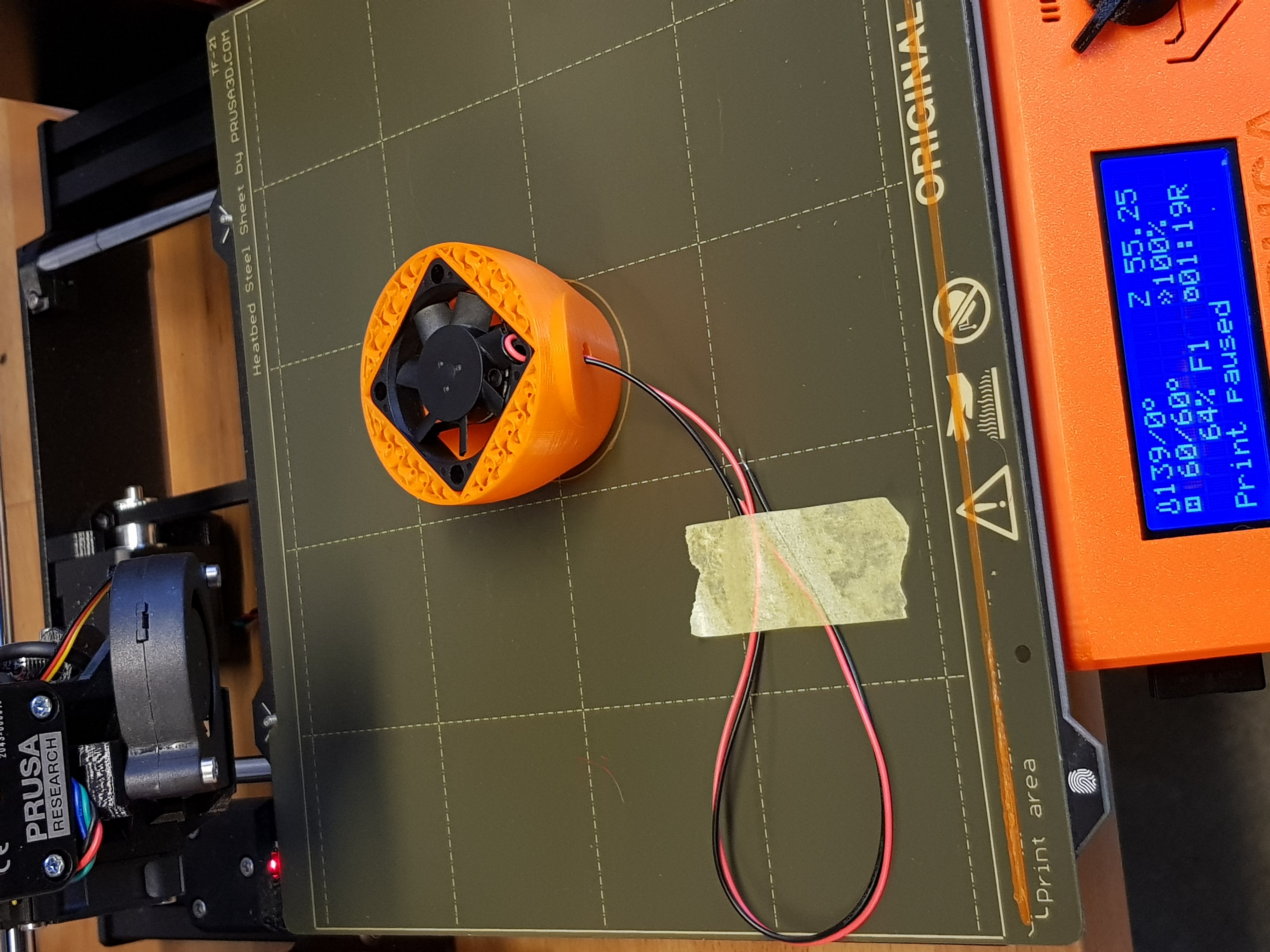
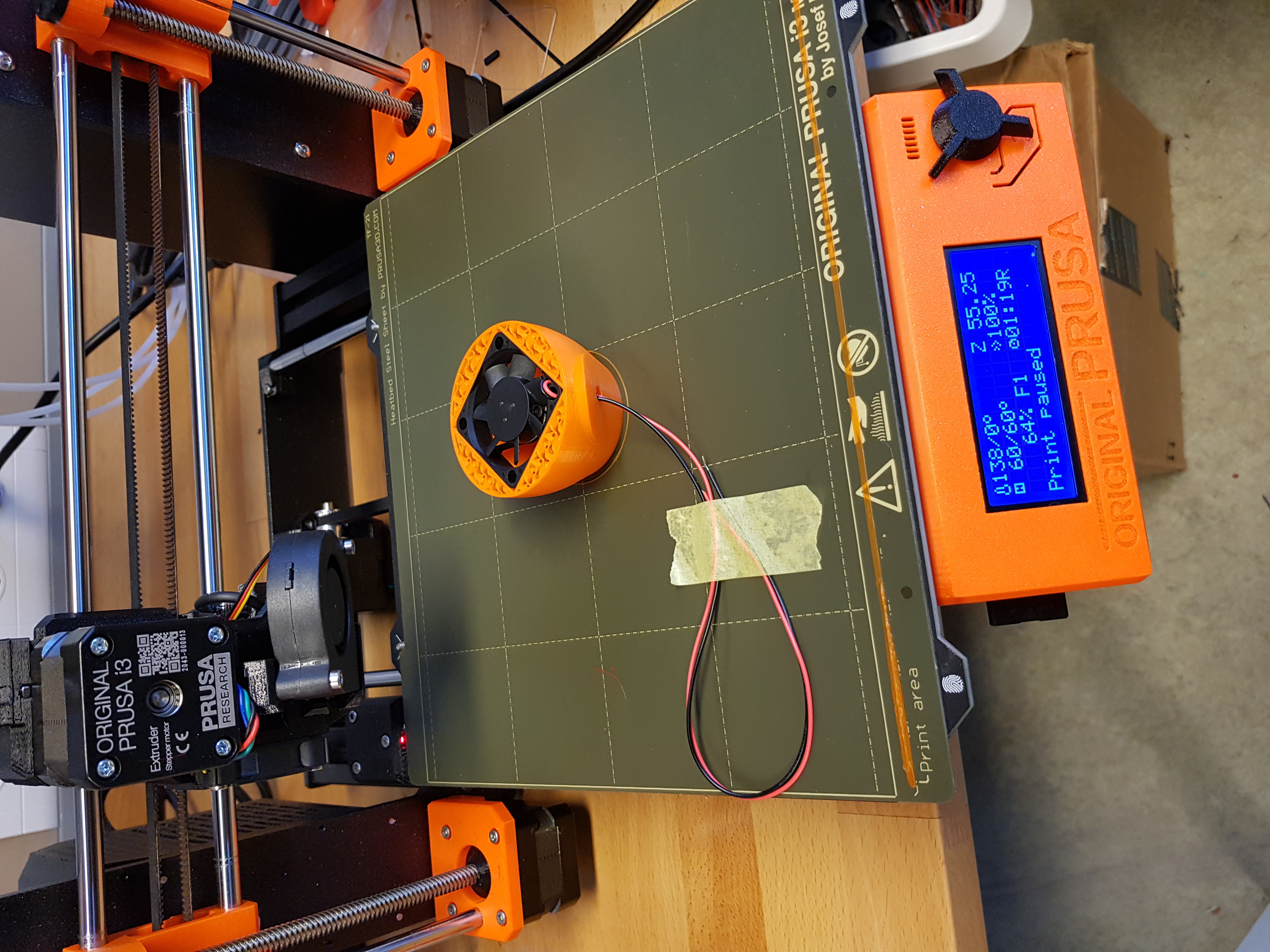
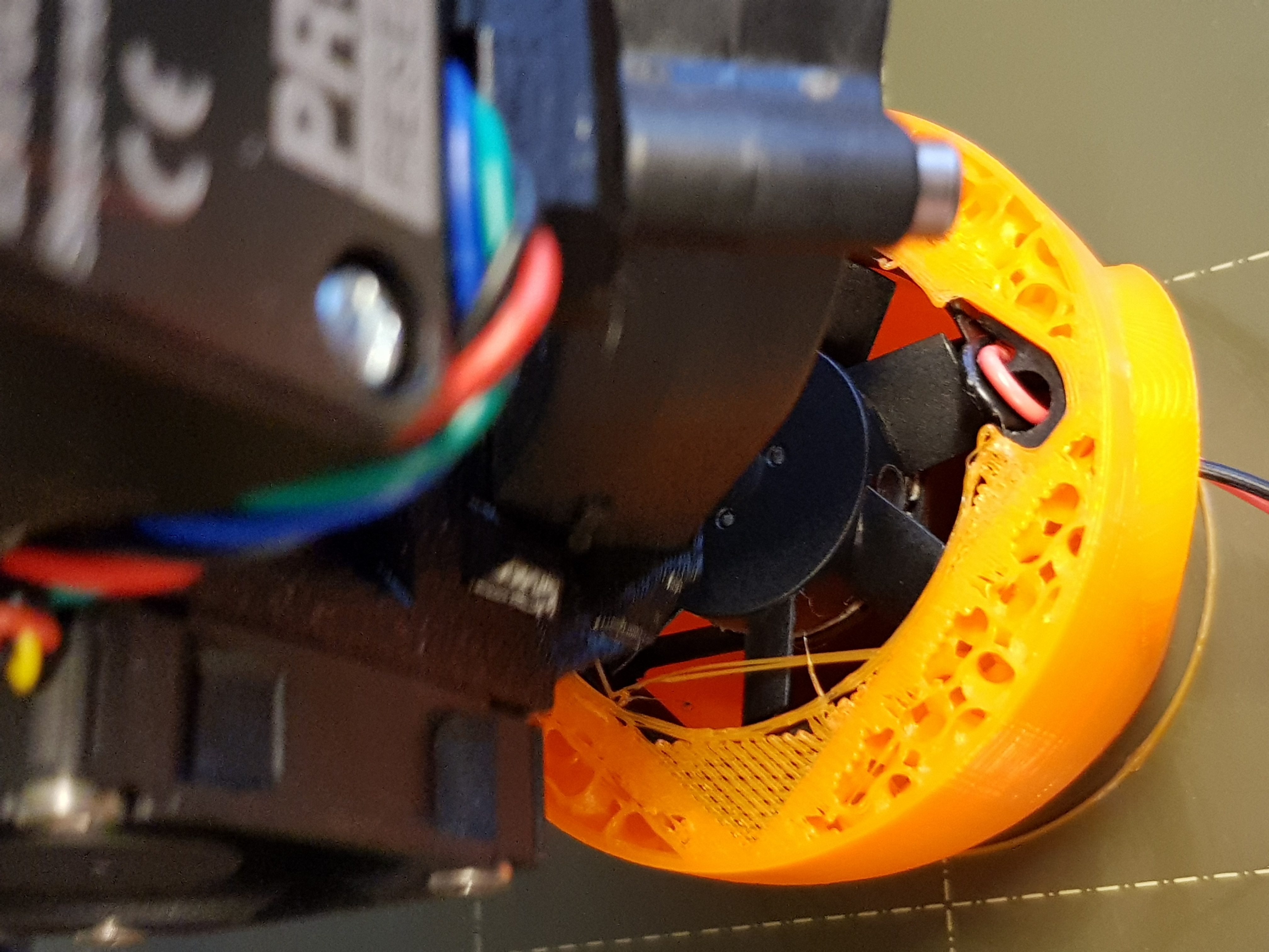
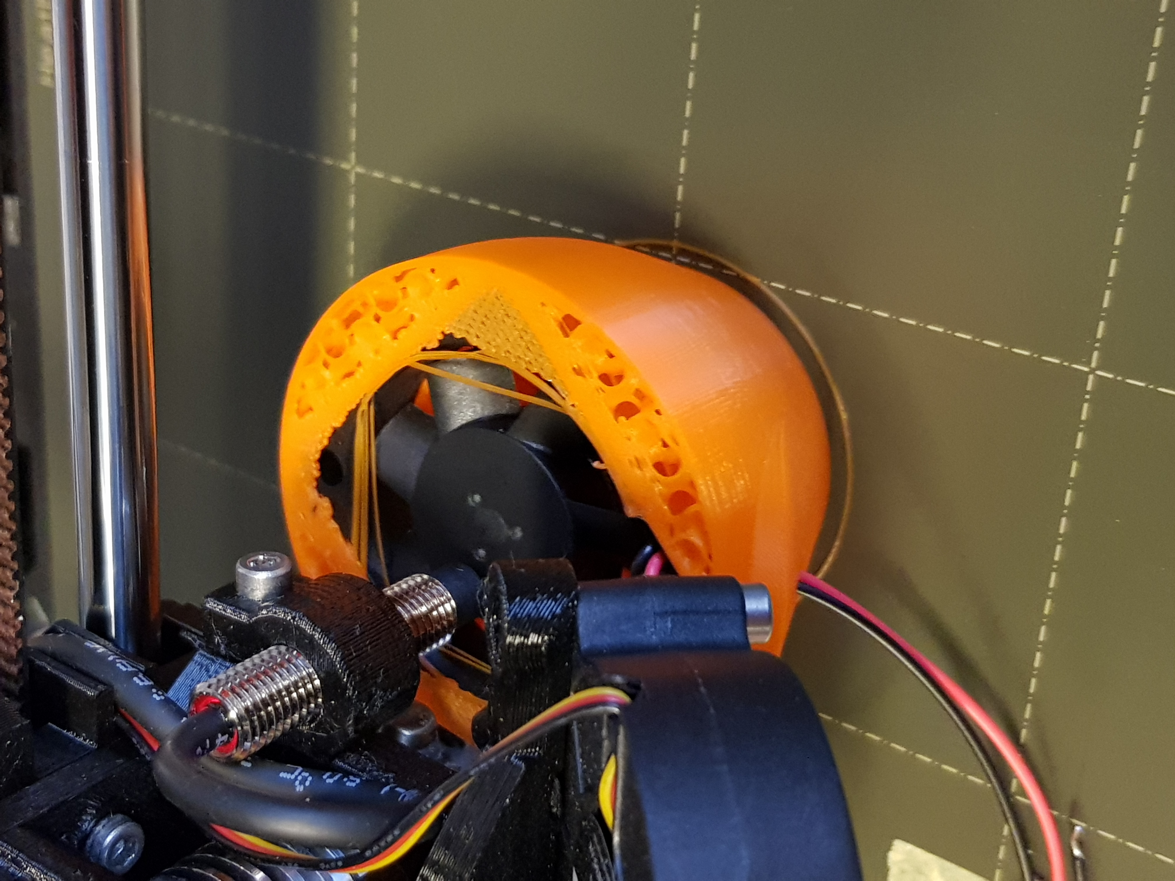
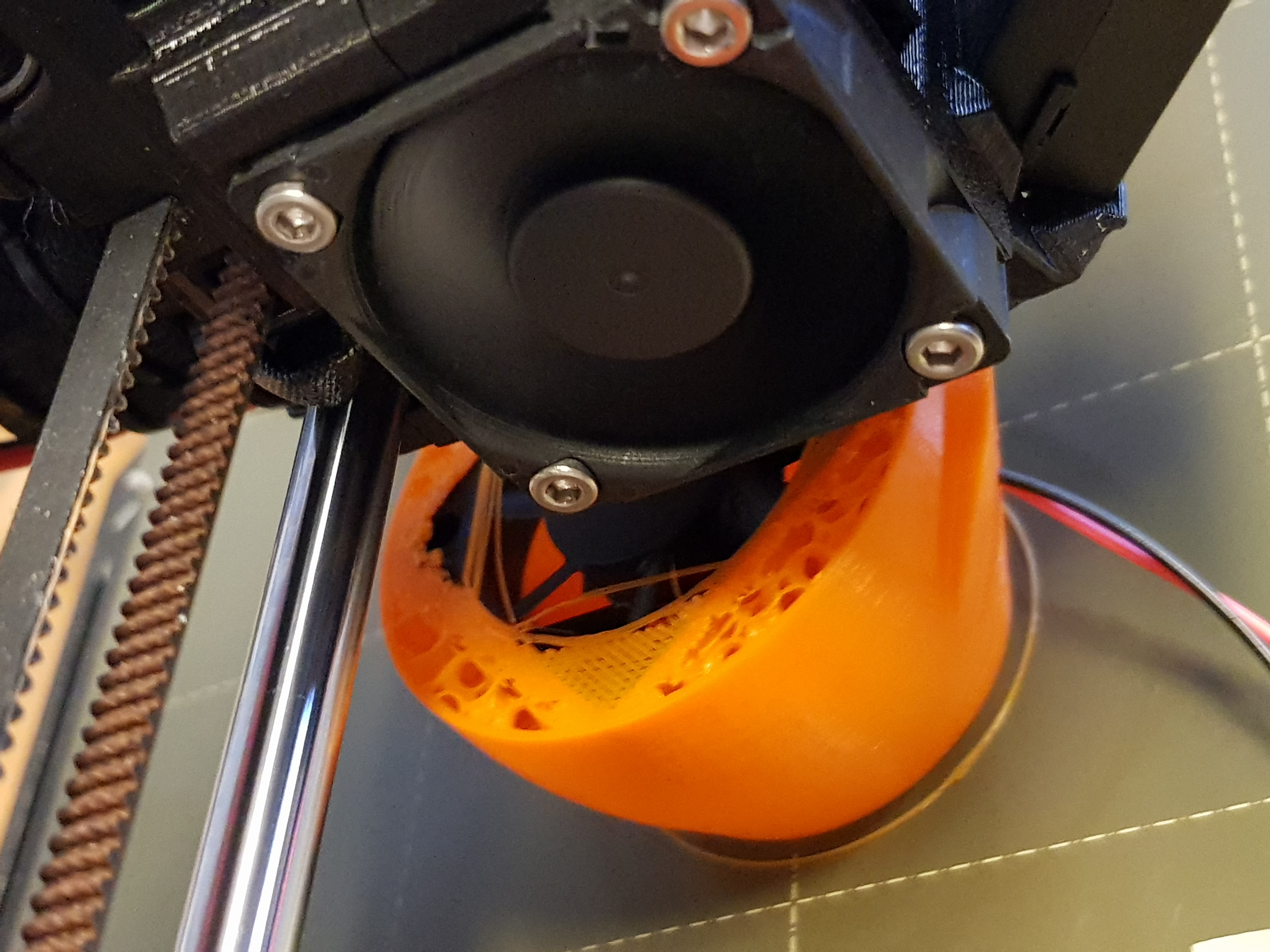
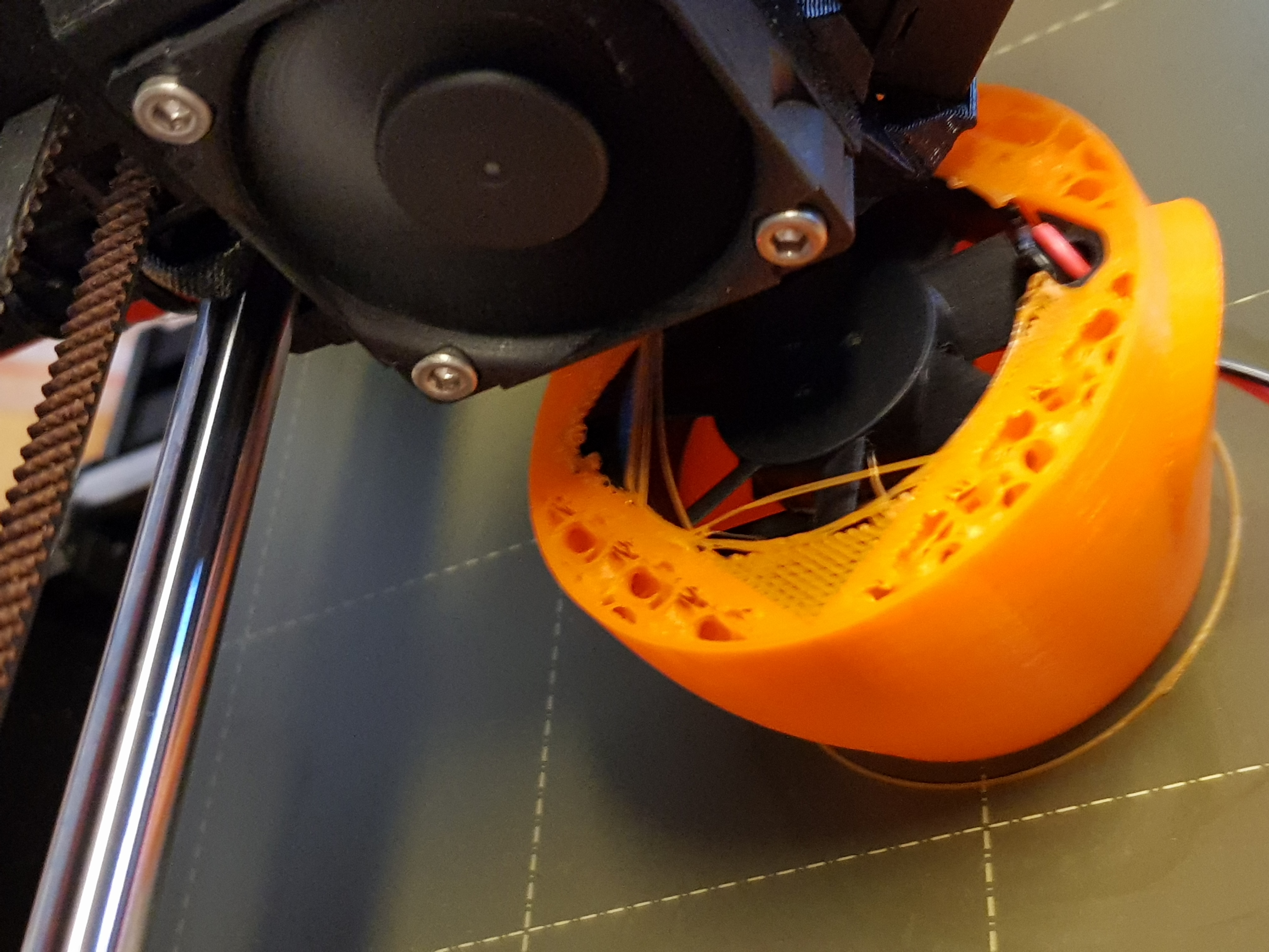
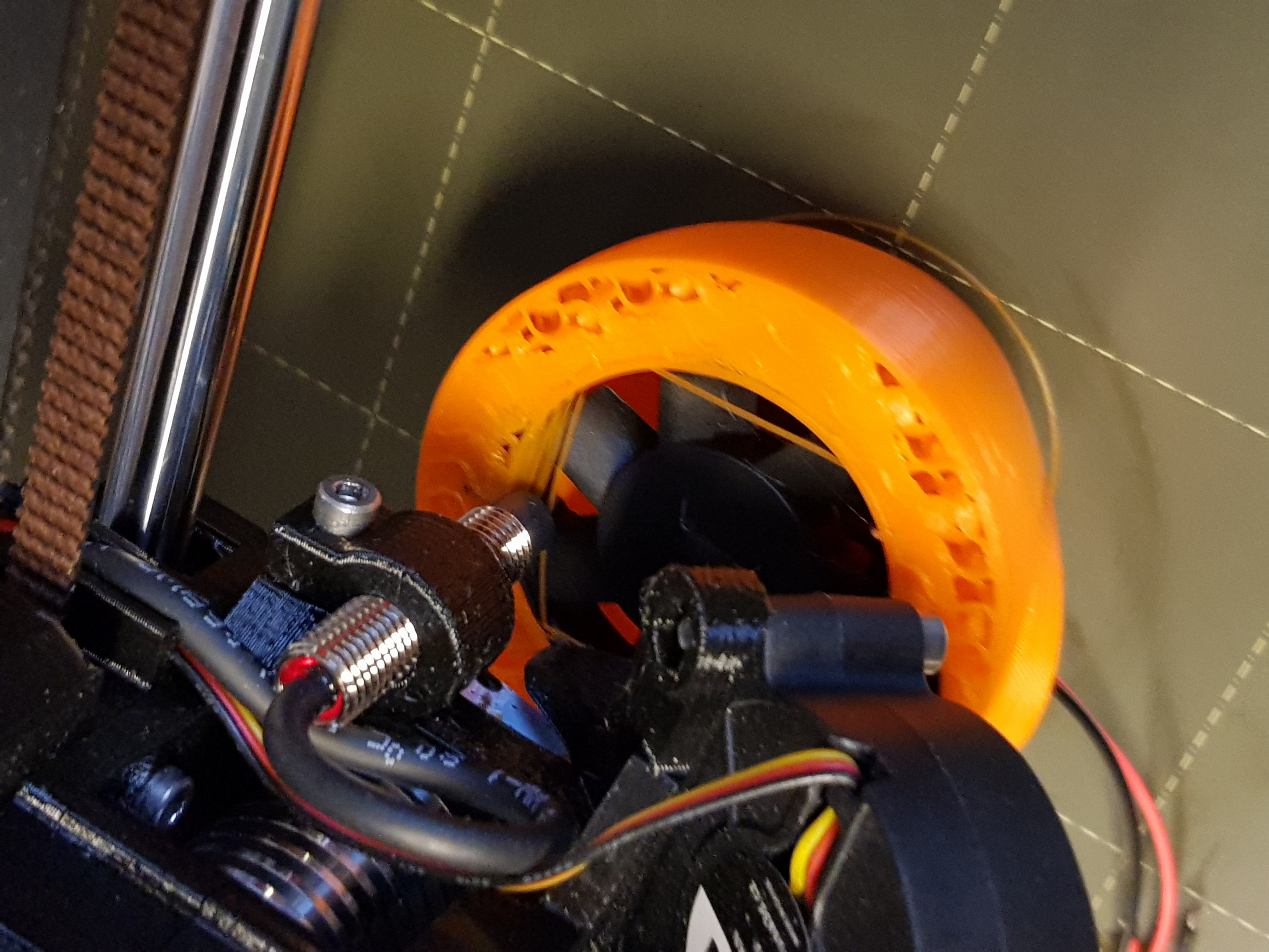
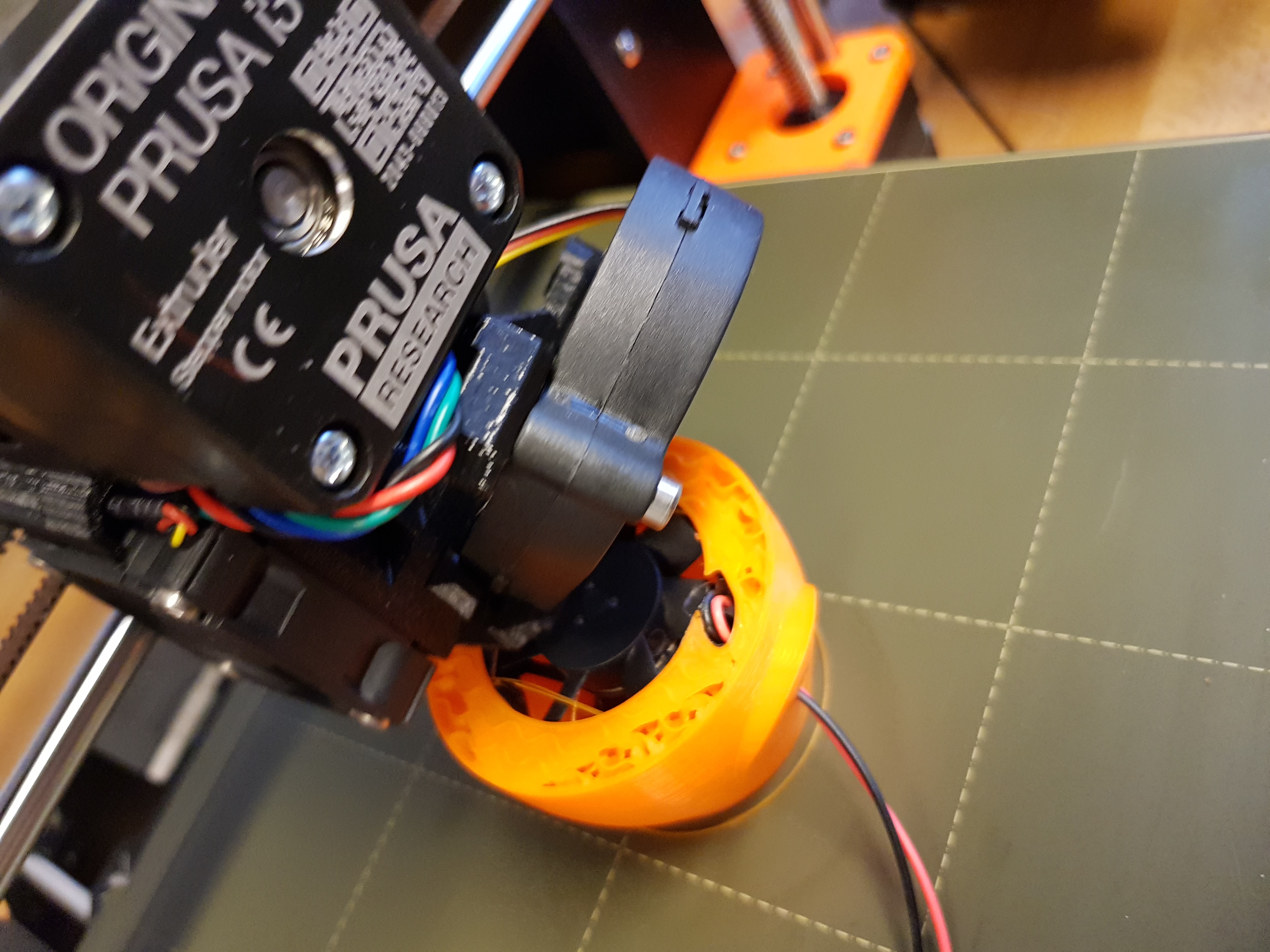
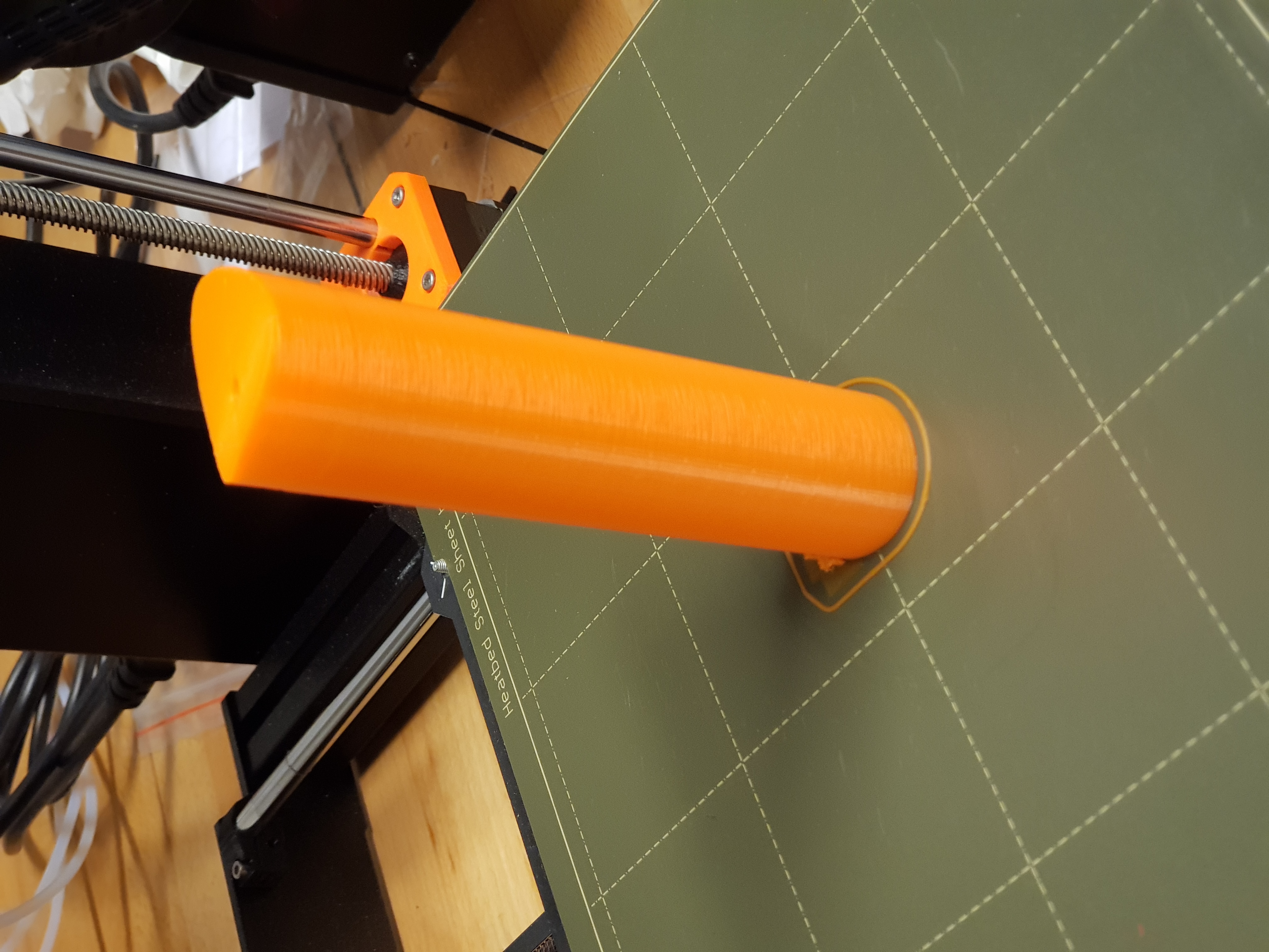
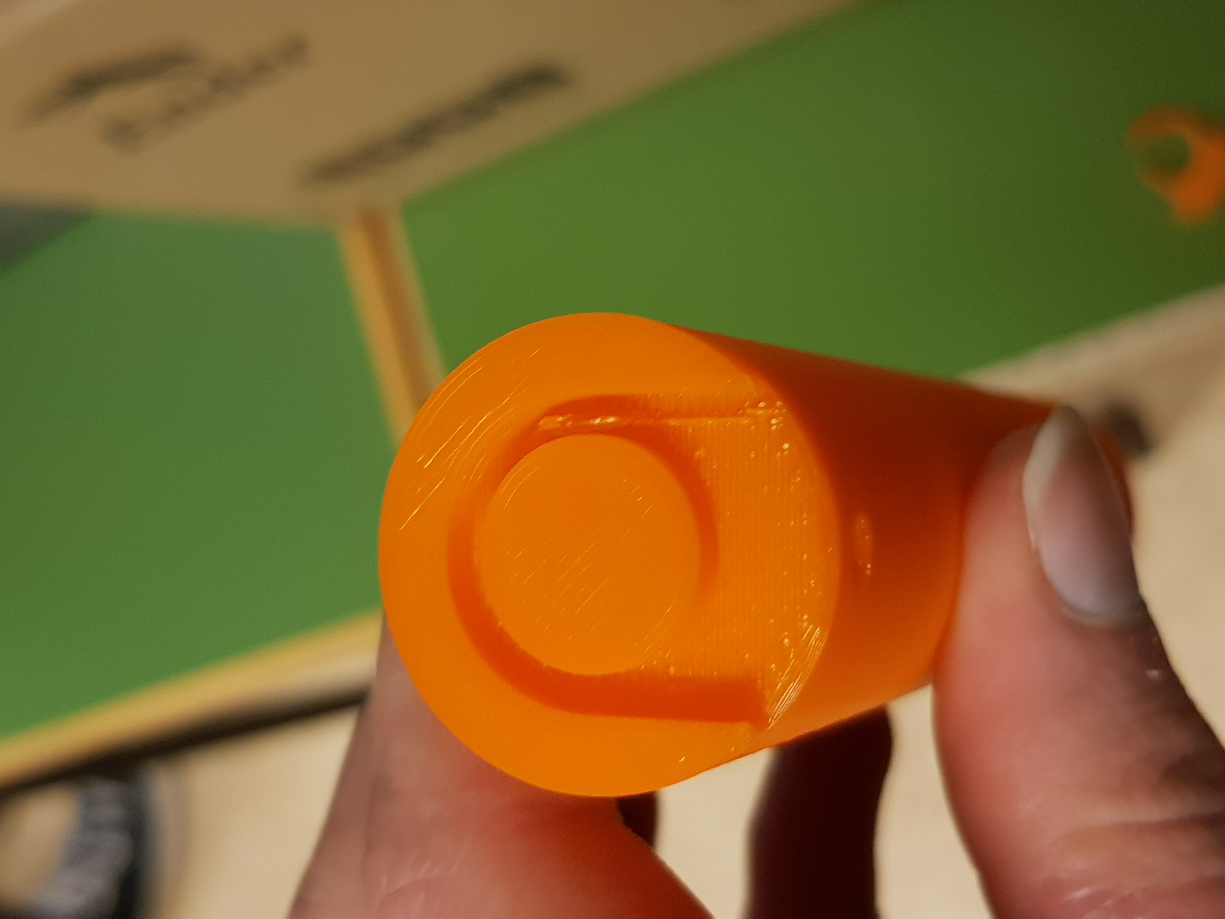
Printing the duct
The printer was finally in a good condition, so I printed the duct. The printer stopped at the correct layer and did a great job printing over the fan, even though the PLA did not stick to the ABS of the fan. I was not sure that the printer was capable of doing it, but it sure did. When the print was paused, I routed the wires, installed the fan, and pressed the knob on the printer to resume. When the print was finished, I only had to remove a few strings over the middle section. I of course whatched carefully during the time the printer printed over the fan.

Worktime: 3 hours.
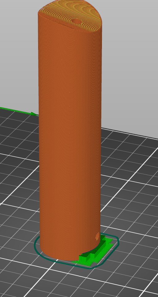
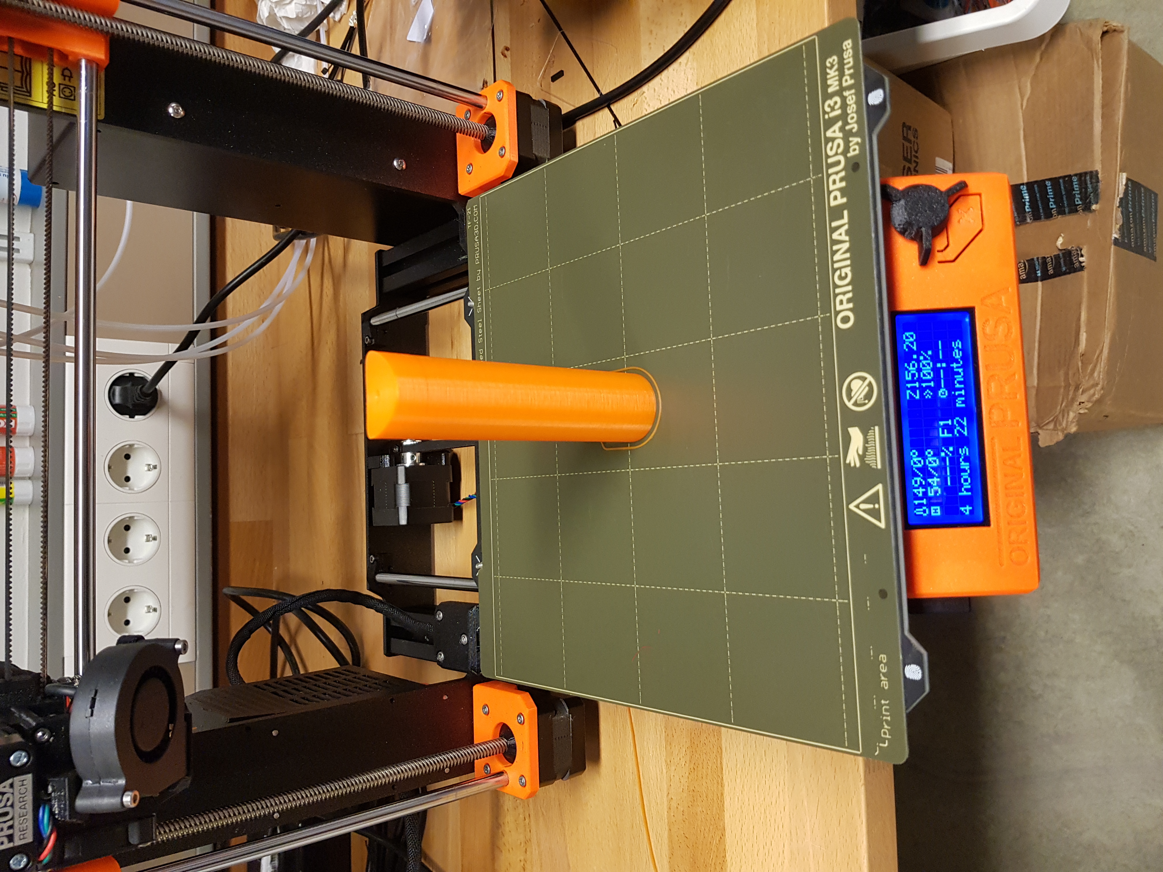
Printing the pole
When the duct was done, I printed the pole for the duct to stand on. Due to the poles internal cavity, wirerouting and fastening mechanism at the bottom, the only way to manufacture it in one piece is 3D printing. I went through the same process, except for drawing, because I drew the pole and the duct as one piece. This time the process was hazzlefree without any mistakes and fails.
Worktime: 4.5 hours.
Total worktime for project 3
- Part 1: 3.2 hours
- Part 2: 33.7 hours
- Documentation: 4.3 hours
TOTAL: 41.2 hours.